Category:VAX 11/730
Jump to navigation
Jump to search
Media in category "VAX 11/730"
The following 200 files are in this category, out of 200 total.
-
 Air Flow Sensor Fitted.jpg 4,608 × 3,456; 3.57 MB
-
 Air Flow Sensor PCB.jpg 4,608 × 3,456; 3.42 MB
-
 Assembling Rack Top Panel.jpg 3,456 × 4,608; 2.76 MB
-
 Backplane Cover.jpg 4,608 × 3,456; 3.46 MB
-
 Backplane Socket Side.jpg 4,608 × 3,456; 3.3 MB
-
 Backplane Solder Side.jpg 4,608 × 3,456; 3.39 MB
-
 Boot Switch Fitted.jpg 4,608 × 3,456; 3.35 MB
-
 Brace fitted.jpg 3,456 × 4,608; 3.4 MB
-
 Cable Clamps.jpg 4,608 × 3,456; 3.51 MB
-
 Cable Guide.jpg 4,608 × 3,456; 3.37 MB
-
 Cable Tray and CPU slides.jpg 3,456 × 4,608; 3.5 MB
-
 Cable Tray Stud Plates.jpg 4,608 × 3,456; 3.42 MB
-
 Cables in Tray.jpg 4,608 × 3,456; 3.43 MB
-
 Card Guide Parts.jpg 4,608 × 3,456; 3.41 MB
-
 Cardcage fitted.jpg 4,608 × 3,456; 3.34 MB
-
 Cardcage.jpg 4,608 × 3,456; 3.37 MB
-
 Catch Pan.jpg 4,608 × 3,456; 3.27 MB
-
 Checking R80 and Power Controller fit.jpg 4,608 × 3,456; 3.47 MB
-
 Checking TU58 Read Amplitude.jpg 4,608 × 3,456; 3.44 MB
-
 Circuit Breaker Voltage Selector.jpg 4,608 × 3,456; 3.44 MB
-
 Comms Regulator.jpg 4,608 × 3,456; 3.46 MB
-
 Connector Panel Brackets.jpg 4,608 × 3,456; 3.41 MB
-
 Connector Panel Frame.jpg 4,608 × 3,456; 3.32 MB
-
 Console Cable DB25 Socket.jpg 4,608 × 3,456; 3.63 MB
-
 Console Cable Hood.jpg 4,608 × 3,456; 3.34 MB
-
 Console Cable Prepared End.jpg 4,608 × 3,456; 3.5 MB
-
 Console Cable.jpg 4,608 × 3,456; 3.52 MB
-
 CPU and Tape Bulkhead parts.jpg 4,608 × 3,456; 3.36 MB
-
 CPU and Tape Bulkheads fitted.jpg 4,608 × 3,456; 3.48 MB
-
 CPU and Tape Bulkheads.jpg 4,608 × 3,456; 3.61 MB
-
 CPU Chassis fitted.jpg 3,456 × 4,608; 3.39 MB
-
 CPU fitted.jpg 4,608 × 3,456; 3.39 MB
-
 CPU Power Cable fitted.jpg 4,608 × 3,456; 3.38 MB
-
 CPU Power Cable.jpg 4,608 × 3,456; 3.31 MB
-
 DMF32 Bulkhead fitted.jpg 4,608 × 3,456; 3.37 MB
-
 DMF32 Bulkhead parts.jpg 4,608 × 3,456; 3.66 MB
-
 DMF32 Bulkhead PCB.jpg 4,608 × 3,456; 3.66 MB
-
 DMF32 Bulkhead.jpg 4,608 × 3,456; 3.37 MB
-
 DMF32 Filters fitted.jpg 4,608 × 3,456; 3.7 MB
-
 Drilling Grub Screw Hole TU58 Roller first try.jpg 4,608 × 3,456; 3.46 MB
-
 Drilling R80 Cable Clamp.jpg 4,608 × 3,456; 3.67 MB
-
 Fan Bearing Parts.jpg 4,608 × 3,456; 3.47 MB
-
 Fan Housing.jpg 4,608 × 3,456; 3.38 MB
-
 Fan Motor PCB.jpg 4,608 × 3,456; 3.57 MB
-
 Fan Stator.jpg 4,608 × 3,456; 3.42 MB
-
 Fischertechnik Tacho Driver top.jpg 4,608 × 3,456; 3.73 MB
-
 Fischertechnik Tacho Driver.jpg 4,608 × 3,456; 3.33 MB
-
 Fitting R80 slides.jpg 4,608 × 3,456; 3.3 MB
-
 Front Fan fitted.jpg 4,608 × 3,456; 3.35 MB
-
 Front of Rack.jpg 3,456 × 4,608; 3.5 MB
-
 Frontpanel assembled.jpg 4,608 × 3,456; 3.53 MB
-
 Frontpanel Console PCB.jpg 4,608 × 3,456; 3.49 MB
-
 Frontpanel Parts.jpg 4,608 × 3,456; 3.36 MB
-
 Frontpanel temporarily fitted.jpg 3,456 × 4,608; 3.47 MB
-
 G7273 Grant M9302 Terminator.jpg 4,608 × 3,456; 6.64 MB
-
 H874 Assembled.jpg 4,608 × 3,456; 3.5 MB
-
 H874 Contactor Assembly.jpg 4,608 × 3,456; 3.41 MB
-
 H874 Contactor Contacts.jpg 4,608 × 3,456; 3.6 MB
-
 H874 Contactor parts.jpg 4,608 × 3,456; 3.54 MB
-
 H874 Control PCB fitted.jpg 4,608 × 3,456; 3.46 MB
-
 H874 Control PCB.jpg 4,608 × 3,456; 3.48 MB
-
 H874 Filter wiring.jpg 4,608 × 3,456; 3.32 MB
-
 H874 fitted.jpg 4,608 × 3,456; 3.54 MB
-
 H874 Mains Connections.jpg 4,608 × 3,456; 3.47 MB
-
 H874 Mains Input parts.jpg 4,608 × 3,456; 3.51 MB
-
 H874 Output Sockets.jpg 4,608 × 3,456; 3.47 MB
-
 H874 Power Bus Cables.jpg 4,608 × 3,456; 3.38 MB
-
 H874 Terminal Cover.jpg 4,608 × 3,456; 3.39 MB
-
 IDC fitted.jpg 4,608 × 3,456; 3.45 MB
-
 Inside TS05 Tacho Arm.jpg 4,608 × 3,456; 3.48 MB
-
 Lock Parts.jpg 4,608 × 3,456; 3.4 MB
-
 M7455 TSU05.jpg 4,608 × 3,456; 6.71 MB
-
 M8388 Integrated Disk Controller.jpg 4,608 × 3,456; 3.31 MB
-
 M8390 Data Path.jpg 4,608 × 3,456; 7.04 MB
-
 M8391 Memory Control and Timing.jpg 4,608 × 3,456; 7.1 MB
-
 M8394 Writeable Control Store.jpg 4,608 × 3,456; 3.52 MB
-
 M8396 DMF32.jpg 4,608 × 3,456; 6.48 MB
-
 M8750 Memory.jpg 4,608 × 3,456; 6.97 MB
-
 Magnetic Catch fitted.jpg 4,608 × 3,456; 3.44 MB
-
 Magnetic Catch parts.jpg 4,608 × 3,456; 3.44 MB
-
 Magnetic Catch.jpg 4,608 × 3,456; 3.35 MB
-
 Mains Cable Bracket upside-down.jpg 3,456 × 4,608; 3.4 MB
-
 Mains Cable Brackets.jpg 4,608 × 3,456; 3.33 MB
-
 Mains Filter PSU Parts.jpg 4,608 × 3,456; 3.41 MB
-
 Mains smoothing CFEs.jpg 4,608 × 3,456; 3.75 MB
-
 Memory fitted.jpg 4,608 × 3,456; 3.71 MB
-
 Memory Regulator.jpg 4,608 × 3,456; 3.36 MB
-
 Monitoring TU58 Read Data.jpg 4,608 × 3,456; 3.7 MB
-
 My first working VAX-11 780 setup (2203329938).jpg 3,880 × 2,607; 1.54 MB
-
 Nameplate (VAX 11-730).jpg 4,608 × 3,456; 3.47 MB
-
 Nameplate Bracket.jpg 4,608 × 3,456; 3.34 MB
-
 National Semiconductor Memory.jpg 4,608 × 3,456; 6.58 MB
-
 New Boot Switch Actuator.jpg 4,608 × 3,456; 3.35 MB
-
 New Mains Cable.jpg 4,608 × 3,456; 3.51 MB
-
 New R80 Cable Clamp.jpg 4,608 × 3,456; 3.34 MB
-
 New TU58 Rollers first try.jpg 4,608 × 3,456; 3.27 MB
-
 Power control fixings.jpg 3,456 × 4,608; 3.44 MB
-
 Power Distribution PCB.jpg 4,608 × 3,456; 3.36 MB
-
 Power Switch Parts.jpg 4,608 × 3,456; 3.41 MB
-
 PSU fitted.jpg 4,608 × 3,456; 3.36 MB
-
 PSU Mainboard.jpg 4,608 × 3,456; 3.38 MB
-
 R80 Cable Clamped.jpg 4,608 × 3,456; 3.45 MB
-
 R80 Chassis in place.jpg 3,456 × 4,608; 3.52 MB
-
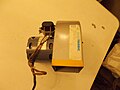
 Rear Fan Assembly.jpg 4,608 × 3,456; 3.23 MB
-
 Rear Fan Parts.jpg 4,608 × 3,456; 3.43 MB
-
 Rear Fans Fitted.jpg 4,608 × 3,456; 3.54 MB
-
 Retractor Sheet.jpg 4,608 × 3,456; 3.52 MB
-
 RH Half Cable Tray.jpg 4,608 × 3,456; 3.27 MB
-
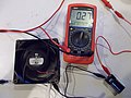 Testing Front Fan.jpg 4,608 × 3,456; 3.56 MB
-
 Testing TS05 Motor.jpg 4,608 × 3,456; 3.41 MB
-
 Testing TS05 PSU.jpg 4,608 × 3,456; 3.26 MB
-
 Testing TS05 Tacho Arm.jpg 4,608 × 3,456; 3.47 MB
-
 Top Panel fitted.jpg 3,456 × 4,608; 2.99 MB
-
 Top Panel open.jpg 3,456 × 4,608; 3.46 MB
-
 Top Trims fitted.jpg 4,608 × 3,456; 3.53 MB
-
 Tracing TU58 Fault.jpg 4,608 × 3,456; 3.52 MB
-
 TS05 Air Capacitor.jpg 4,608 × 3,456; 3.38 MB
-
 TS05 Air Duct parts.jpg 4,608 × 3,456; 3.48 MB
-
 TS05 Air Ducts.jpg 4,608 × 3,456; 3.78 MB
-
 TS05 Air Intake Bracket.jpg 4,608 × 3,456; 3.39 MB
-
 TS05 Chassis fitted.jpg 3,456 × 4,608; 3.55 MB
-
 TS05 Compliance Arm parts.jpg 4,608 × 3,456; 3.56 MB
-
 TS05 Compliance Arm.jpg 4,608 × 3,456; 3.41 MB
-
 TS05 Deck fitted.jpg 3,456 × 4,608; 3.33 MB
-
 TS05 Door fitted.jpg 4,608 × 3,456; 3.39 MB
-
 TS05 Door Hinge Spring.jpg 4,608 × 3,456; 3.49 MB
-
 TS05 Door Lock parts.jpg 4,608 × 3,456; 3.42 MB
-
 TS05 Door Lock.jpg 4,608 × 3,456; 3.43 MB
-
 TS05 Door Parts.jpg 4,608 × 3,456; 3.42 MB
-
 TS05 Door Remains.jpg 4,608 × 3,456; 3.55 MB
-
 TS05 Fan parts.jpg 4,608 × 3,456; 3.48 MB
-
 TS05 Fan.jpg 4,608 × 3,456; 3.59 MB
-
 TS05 Front Air Jet parts.jpg 4,608 × 3,456; 3.57 MB
-
 TS05 Front Air Jet.jpg 4,608 × 3,456; 3.42 MB
-
 TS05 Front Panel fitted.jpg 4,608 × 3,456; 3.51 MB
-
 TS05 Guide parts.jpg 4,608 × 3,456; 3.38 MB
-
 TS05 Hub Lock Bellcrank fitted.jpg 4,608 × 3,456; 3.65 MB
-
 TS05 Hub Lock Bellcrank parts.jpg 4,608 × 3,456; 3.49 MB
-
 TS05 Hub Lock Bellcrank.jpg 4,608 × 3,456; 3.53 MB
-
 TS05 Hub Lock Cam.jpg 4,608 × 3,456; 3.53 MB
-
 TS05 Hub Lock Solenoid.jpg 4,608 × 3,456; 3.51 MB
-
 TS05 Interface Area.jpg 4,608 × 3,456; 3.5 MB
-
 TS05 Logic PCB.jpg 4,608 × 3,456; 3.63 MB
-
 TS05 Mains Filter.jpg 4,608 × 3,456; 3.38 MB
-
 TS05 Mains Plug.jpg 4,608 × 3,456; 3.32 MB
-
 TS05 Mains Transformer.jpg 4,608 × 3,456; 3.43 MB
-
 TS05 Motor Commutator.jpg 4,608 × 3,456; 3.54 MB
-
 TS05 Motor parts.jpg 4,608 × 3,456; 3.57 MB
-
 TS05 Motor Top End.jpg 4,608 × 3,456; 3.61 MB
-
 TS05 PCB fitted.jpg 3,456 × 4,608; 3.37 MB
-
 TS05 PCB Rails.jpg 4,608 × 3,456; 3.46 MB
-
 TS05 Processor Area.jpg 4,608 × 3,456; 3.37 MB
-
 TS05 PSU Casing.jpg 4,608 × 3,456; 3.5 MB
-
 TS05 PSU Cover fitted.jpg 4,608 × 3,456; 3.46 MB
-
 TS05 PSU Housing fitted.jpg 4,608 × 3,456; 3.45 MB
-
 TS05 PSU PCB connected.jpg 4,608 × 3,456; 3.3 MB
-
 TS05 PSU PCB fitted.jpg 4,608 × 3,456; 3.43 MB
-
 TS05 PSU PCB.jpg 4,608 × 3,456; 3.47 MB
-
 TS05 Read Area.jpg 4,608 × 3,456; 3.44 MB
-
 TS05 Reel Detect Sensor.jpg 4,608 × 3,456; 3.42 MB
-
 TS05 Reel Height Tool parts.jpg 4,608 × 3,456; 3.51 MB
-
 TS05 Reel Height Tools.jpg 4,608 × 3,456; 3.4 MB
-
 TS05 Roller Guide parts.jpg 4,608 × 3,456; 3.3 MB
-
 TS05 Sensor Area.jpg 4,608 × 3,456; 3.46 MB
-
 TS05 Sensors fitted.jpg 4,608 × 3,456; 3.47 MB
-
 TS05 Sensors.jpg 4,608 × 3,456; 3.45 MB
-
 TS05 Servo Area.jpg 4,608 × 3,456; 3.48 MB
-
 TS05 Setting Reel Height Tool.jpg 4,608 × 3,456; 3.41 MB
-
 TS05 Slides.jpg 4,608 × 3,456; 3.46 MB
-
 TS05 Supply Hub fitting.jpg 4,608 × 3,456; 3.39 MB
-
 TS05 Supply Hub parts.jpg 4,608 × 3,456; 3.49 MB
-
 TS05 Tacho Arm fitted.jpg 4,608 × 3,456; 3.54 MB
-
 TS05 Tacho Arm parts.jpg 4,608 × 3,456; 3.43 MB
-
 TS05 Tacho Arm Sensor.jpg 4,608 × 3,456; 3.53 MB
-
 TS05 Tacho Interface Tester.jpg 4,608 × 3,456; 3.49 MB
-
 TS05 Takeup Hub fitting.jpg 4,608 × 3,456; 3.36 MB
-
 TS05 Top Cover assembled.jpg 4,608 × 3,456; 3.37 MB
-
 TS05 Top Cover fitted.jpg 4,608 × 3,456; 3.64 MB
-
 TS05 Top Cover parts.jpg 4,608 × 3,456; 3.65 MB
-
 TS05 Write Protect Sensor.jpg 4,608 × 3,456; 3.44 MB
-
 TU58 Cartridge Belt.jpg 4,608 × 3,456; 3.56 MB
-
 TU58 Cartridge Open.jpg 4,608 × 3,456; 3.34 MB
-
 TU58 Chassis assembled.jpg 4,608 × 3,456; 3.58 MB
-
 TU58 Chassis fitted.jpg 4,608 × 3,456; 3.37 MB
-
 TU58 Chassis parts.jpg 4,608 × 3,456; 3.56 MB
-
 TU58 Controller Connections.jpg 4,608 × 3,456; 3.56 MB
-
 TU58 Controller PCB.jpg 4,608 × 3,456; 3.5 MB
-
 TU58 Drive parts.jpg 4,608 × 3,456; 3.45 MB
-
 TU58 Drives in Chassis.jpg 4,608 × 3,456; 3.38 MB
-
 TU58 Earth Wires.jpg 4,608 × 3,456; 3.48 MB
-
 TU58 Mounting Screws.jpg 4,608 × 3,456; 3.48 MB
-
 TU58 New Roller and Cartridge.jpg 4,608 × 3,456; 3.6 MB
-
 TU58 New Roller fitted.jpg 4,608 × 3,456; 3.52 MB
-
 TU58 Old Roller.jpg 4,608 × 3,456; 3.31 MB
-
 TU58 Roller Parts first try.jpg 4,608 × 3,456; 3.37 MB
-
 TU58 Tacho.jpg 4,608 × 3,456; 3.46 MB
-
 TU58 without Roller.jpg 4,608 × 3,456; 3.48 MB
-
 Turning TU58 Roller first try.jpg 4,608 × 3,456; 3.81 MB
-
 Unibus PCBs fitted.jpg 4,608 × 3,456; 3.28 MB
-
 Wiring TS05 Plug.jpg 4,608 × 3,456; 3.51 MB


.jpg)
.jpg)


