Category:Scans from 'Heat Engines', 1913
Jump to navigation
Jump to search
Summary
| Description | Scans from a 1909 engineering textbook |
| Source | Scan from Prof. William Ripper, Sheffield Univ. d.1937 (1913 edition of 1909 book. Originally published in 1889 as "Steam", but later expanded to cover internal combustion engines and so re-titled.) Heat Engines, London: Longmans |
| Author | Andy Dingley (scanner) |
| Other versions |
.jpg) |
Pages in category "Scans from 'Heat Engines', 1913"
This category contains only the following page.
Media in category "Scans from 'Heat Engines', 1913"
The following 72 files are in this category, out of 72 total.
-

-
 18-24hp Enfield engine, side-section (Heat Engines, 1913).jpg 907 × 584; 129 KB
-
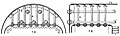
 Babcock and Wilcox boiler (Heat Engines, 1913).jpg 943 × 727; 139 KB
-
 Babcock and Wilcox boiler, section (Heat Engines, 1913).jpg 974 × 742; 197 KB
-
 Boiler firebox crown girder stay (Heat Engines, 1913).jpg 558 × 258; 21 KB
-
 Boiler firebox crown stays (Heat Engines, 1913).jpg 1,410 × 424; 81 KB
-
 Boiler gusset stay (Heat Engines, 1913).jpg 440 × 232; 14 KB
-
 Boiler watergauge (Heat Engines, 1913).jpg 402 × 810; 37 KB
-
 Boiling water (Heat Engines, 1913).jpg 462 × 636; 50 KB
-
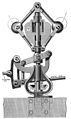 Centrifugal governor (Heat Engines, 1913).jpg 796 × 1,336; 214 KB
-
-

-
 Connecting rod big-end, wedged cotter (Heat Engines, 1913).jpg 674 × 440; 37 KB
-
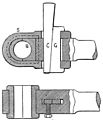 Connecting rod end, strapped (Heat Engines, 1913).jpg 628 × 730; 76 KB
-
 Connecting rod ends, bolted (Heat Engines, 1913).jpg 844 × 590; 64 KB
-
 Corliss cylinder (Heat Engines, 1913).jpg 1,424 × 886; 140 KB
-
 Corliss cylinder section.jpg 813 × 608; 91 KB
-
 Corliss engine side view (Heat Engines, 1913).jpg 1,128 × 606; 80 KB
-
 Corliss valvegear, trip-gear (Heat Engines, 1913).jpg 704 × 434; 66 KB
-
 Cornish boiler, end-section (Heat Engines, 1913).jpg 638 × 722; 111 KB
-
 Cornish boiler, side-section (Heat Engines, 1913).jpg 409 × 179; 21 KB
-
 Cross compound engine, end section (Heat Engines, 1913).jpg 624 × 584; 63 KB
-
 Cross compound engine, plan section (Heat Engines, 1913).jpg 1,171 × 747; 174 KB
-
 Curtis turbine, pressure - velocity diagram (Heat Engines, 1913).jpg 283 × 484; 37 KB
-

-
 Cylinder drain cocks (Heat Engines, 1913).jpg 276 × 134; 6 KB
-
 De Laval turbine wheel (Heat Engines, 1913).jpg 226 × 286; 14 KB
-
-
 Deadweight safety valve section (Heat Engines, 1913).jpg 215 × 354; 17 KB
-
 Eccentric and sheave (Heat Engines, 1913).png 410 × 581; 15 KB
-
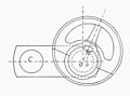 Eccentric on crankshaft (Heat Engines, 1913).jpg 680 × 505; 28 KB
-
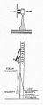
 Frontispiece (Heat Engines, 1913).jpg 356 × 566; 33 KB
-
 Galloway tubes, section (Heat Engines, 1913).jpg 237 × 261; 15 KB
-
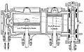
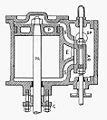
 Hornsby gas engine, section (Heat Engines, 1913).jpg 745 × 492; 58 KB
-
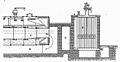 Lancashire boiler economizer, section (Heat Engines, 1913).jpg 717 × 372; 64 KB
-
 Lancashire boiler furnace (Heat Engines, 1913).jpg 458 × 190; 18 KB
-
 Lancashire boiler, end view and section (Heat Engines, 1913).jpg 723 × 449; 80 KB
-
 Lancashire boiler, side section (Heat Engines, 1913).jpg 736 × 389; 41 KB
-
 Lever safety valve (Heat Engines, 1913).jpg 409 × 212; 13 KB
-
 Locomotive boiler, section (Heat Engines, 1913).jpg 1,219 × 726; 73 KB
-
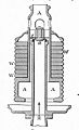
 Mirrlees Diesel oil engine (Heat Engines, 1913).jpg 480 × 558; 49 KB
-

-
 Newcomen atmospheric engine (Heat Engines, 1913).jpg 843 × 790; 65 KB
-
 Piston, half-section (Heat Engines, 1913).jpg 256 × 166; 9 KB
-
 Piston, section (Heat Engines, 1913).jpg 485 × 384; 36 KB
-
 Piston, sprung ring (Heat Engines, 1913).jpg 316 × 262; 20 KB
-
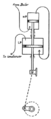
 Pulsometer (Heat Engines, 1913).jpg 324 × 599; 106 KB
-
 Quadruple expansion compound, end view (Heat Engines, 1913).jpg 486 × 686; 54 KB
-
 Quadruple expansion compound, section (Heat Engines, 1913).jpg 407 × 693; 61 KB
-
 Ramsbottom safety valve (side only) (Heat Engines, 1913).jpg 280 × 333; 20 KB
-
 Ramsbottom safety valve, section (Heat Engines, 1913).jpg 448 × 333; 33 KB
-
 Rateau turbine, pressure - velocity diagram (Heat Engines, 1913).jpg 369 × 546; 34 KB
-
 Schmidt superheater (Heat Engines, 1913).jpg 987 × 754; 117 KB
-
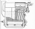
 Single flue vertical boiler (Heat Engines, 1913).jpg 456 × 414; 28 KB
-
 Slide-valve cylinder, section (Heat Engines, 1913).jpg 472 × 530; 44 KB
-
 Slide-valve cylinder, three-quarter view (Heat Engines, 1913).jpg 371 × 353; 30 KB
-
 Slipper guide crosshead (Heat Engines, 1913).jpg 804 × 491; 32 KB
-
 Steam condenser air pump (Heat Engines, 1913).jpg 543 × 640; 46 KB
-
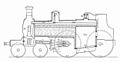 Steam locomotive, side section (Heat Engines, 1913).jpg 1,246 × 647; 75 KB
-
 Steam locomotive, vertical half-section (Heat Engines, 1913).jpg 1,284 × 231; 32 KB
-
 Stephenson link motion (Heat Engines, 1913).jpg 448 × 280; 20 KB
-
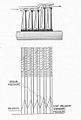
 Stirling boiler (Heat Engines, 1913).jpg 1,610 × 1,246; 432 KB
-
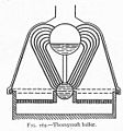 Thornycroft boiler, diagram (Heat Engines, 1913).jpg 260 × 279; 17 KB
-
 Thornycroft boiler, end-view (Heat Engines, 1913).jpg 496 × 427; 53 KB
-
 Thornycroft boiler, side (Heat Engines, 1913).jpg 544 × 447; 46 KB
-
 Vertical slide-valve engine, end view (Heat Engines, 1913).jpg 677 × 1,040; 57 KB
-
 Vertical slide-valve engine, section (Heat Engines, 1913).jpg 508 × 1,042; 69 KB
-
 Woolf compound engine working principle (Heat Engines, 1913).png 188 × 438; 11 KB
-
 Woolf compound engine, diagram (Heat Engines, 1913).jpg 188 × 454; 11 KB
-
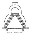 Yarrow boiler, diagram (Heat Engines, 1913).jpg 241 × 278; 12 KB
-
 Yarrow boiler, end view in hull (Heat Engines, 1913).jpg 451 × 439; 37 KB
-
 Zoelly turbine, section (Heat Engines, 1913).jpg 800 × 876; 95 KB
.jpg)
.jpg)
.jpg)
.jpg)
.jpg)
.jpg)
.jpg)
.jpg)
.jpg)
.jpg)
.png)
.jpg)
.jpg)
.jpg)
.jpg)

.jpg)
.jpg)
.jpg)
.jpg)
.jpg)
.jpg)
.jpg)
.jpg)
.jpg)
.jpg)
.jpg)
.png)
.jpg)
.jpg)
.jpg)
.jpg)
.jpg)
.jpg)
.jpg)
.jpg)
.jpg)
.jpg)
.jpg)
.jpg)
.jpg)
.jpg)
.jpg)
.jpg)
.jpg)
.jpg)
_(Heat_Engines,_1913).jpg)
.jpg)
.jpg)
.jpg)
.jpg)
.jpg)
.jpg)
.jpg)
.jpg)
.jpg)
.jpg)
.jpg)
.jpg)
.jpg)
.jpg)
.jpg)
.jpg)
.png)
.jpg)
.jpg)
.jpg)
.jpg)
.jpg)
.jpg)
.jpg)