User:Smallman12q/gallery
Jump to navigation
Jump to search

Wed Jun 13 08:28:44 EDT 2012[edit]
-
Light Bulb Filament. Bill takes apart an incandescent light bulb to how the filament is made. He shows extreme close-ups of the filament, and he discusses the materials processing need to make the ductile tungsten used. Transcript Transcript Now, most of us believe that after Thomas Edison - or Joseph Swan if you're British - invented the light bulb in the 1870s it took off as a useful everyday object, and revolutionized modern lighting. However, Edison's original model used a carbonized bamboo filament: Which was fragile and also didn't burn that brightly. Here's what really made the incandescent light bulb as we know it . It's the fabulous engineering that went into creating the tungsten filaments we see in today's bulbs. Tungsten's perfect because its high melting point allows it to be run at high temperatures. The higher the temperature, the more visible light emitted. The filament seems a simple thing, but let me show you how amazing it is. If we zoom in a bit you can see it's a coil, not just a straight wire, but if we look even closer ... we can see it's a coil within a coil. The filament starts as a wire 20 inches long and about two-thousandth of an inch in diameter. Think of the Sear Tower shrunk to about one and a half inches wide. The filament's then wound into a coil with 1130 turns until it's a bit over three inches long, and then coiled again to the three-quarters of an inch that you see in the bulb. That's the coiled coil I showed you. Obviously the coils enable more wire to glow, but also internal reflections within the coil can double the intensity of the light emitted. As an engineer what amazes me is the ductility needed to make these coils. Let me show you what I mean by ductile: A piece of copper has high ductility: You can bend and then return it to its original shape. No way to do that with natural tungsten: It just .... snaps. To make tungsten ductile it took elegant, creative and careful work by an engineer at General Electric. William Coolidge developed a process for taking tungsten powder and making it into a wire. Just to give you an idea of the difficulty here's an abbreviated list of the steps. One, apply great pressure to turn tungsten powder into a fragile bar. Two, heat it to 1300 degrees Celsius and then cool with water. Three, pass a current thruthe tungsten while heating it to 3200 degree Celsius, & then cool again. Four, heat yet again to 1500 degree Celsius, but this time while flowing hydrogen over it. Five, pass it through a series of dies to cold work it and then hammer it. And then the sixth and final step: heat it and then reduce the temperature gradually while drawing it into a 1 mm diameter wire. I know that's a lot to take in, but take note that Coolidge used empirical observations, intuitions and past knowledge - not purely scientific knowledge of tungsten itself. One last thing. For the filament to last at high temperatures, no oxygen must contact it. Look what happens if I turn on the filament without the glass envelope. I love that! If you take a close look you see the tungsten's now black. That's tungsten oxide. To keep oxygen away from the filament the earliest bulb simply held a vacuum, today we fill them with argon gas. It insulates the filament and keeps it from evaporating thus allowing for even higher temperatures. Although the days of the incandescent light bulb are numbered, with newer and more efficient compact fluorescents and LEDs on the market, I find that these old light bulbs, like many old technologies, illustrate wonderfully creative engineering and problem solving. I'm Bill Hammack, the engineer guy.
Wed Jun 13 08:21:28 EDT 2012[edit]
errors[edit]
- File:Lightbulb-engineerguy.ogv aborted: exists: File:Lightbulb-engineerguy.ogv
-
Cell phone design. Bill uses a pile of cell phones to illustrate the seven design criteria that shape a mobile device. He outlines the seven basic constraints. Transcript Nothing illustrates engineering design better than a mobile phone. In fact, a definition of engineering might be something like "design with real world contraints." Here's the seven major constraints that govern the choices made by an engineer in designing a cell phone. The essential trade-off in any cell phone is compactness versus usability. We want a small phone, but we also want one that fits our bodies. Here's three solutions. A hinge. The classic flip phone - put a hinge in and change the size and it allows you to have larger keys. You can also see this same idea in slider keyboards. Second, you can do what they do on this phone - a Blackberry - and maximize available space by using very tiny keys. And, you can use software. This is my android, the phone I use everyday and I've added to it a clever littled keyboard designed for small devices. I can spell my name just be doing this. Very clever isn't it? Next, emotions affect the design of a cell phone. You don't see these too much today, but the flip of this now nearly vintage phone resonates deeply in the psyche of someone my age. I grew up watching Captain Kirk grab his communicator and bark a command. Beam me up Scotty! I'm sure phones today resonate in some way with video games or popular movies. Now, next, in making a compact design an engineer considers energy. In the twenty years or so that I've been using a cell phone they've shrunk. Hold on. Look at how huge this vintage "brick" phone is from the 1980s. This isn't even one of the first ones: Its one of the later ones called an "ultra classic II", slightly smaller than the first phones. It weights just over a pound and seems to be mostly battery! It uses a nickel-cadmium one. Compare it to this lithium ion from a more modern phone. Now batteries shrunk because they got better - we have greater energy density now - but likely more important is the move from analog to digital signaling, and a movement of much energy-draining computation from the phones themselves to the towers. The next constraint also helped reduce battery size. Old cell phones had brick sized batteries partly because it took a lot of power to reach a cell phone tower; but today we have such a density of towers that we don't need as much energy to reach one. The increase in towers has made this [antenna] a nearly endangered species. For this RAZR this is the closest indication of an antenna: Its a rubber cover for the for the external antenna connector, used during testing of the phone at the factory. The actual antenna is inside underneath one of the plastic parts of the case of the phone. Now, this doesn't work as well as a huge external one, but that's the the trade-off between compactness and usability I mentioned earlier. Now, another reason for the phones compactness is plastics. If we didn't have plastics this phone would be much larger and more expensive. Take just this "latch" imagine how bulky some kind of clasp would be. The fact that this plastic gives a little bit and pops back in to place makes this simple, small fastener possible. The phone's designer needed a deep knowledge about how plastic behaves so that it could be used thousands of times without wearing out. The insides - the way a phone operates - reflects yet a sixth design criteria. On most modern cell phones you'll something called Enhanced or E911: In an emergency an operator can locate the phone to within several hundred feet. Typically it doesn't use true global positioning, but instead "assisted GPS" in that it uses the location of cell phone towers to triangulate. Now, this is fraught with all types of privacy issues. Lastly, we need this phone to quickly change the volume because as a culture we've decided that there are times when our cell phones shouldn't ring. And so we can adjust the ring tone volume easily. I'm Bill Hammack, the engineer guy. Hi, how did you get this number?
-
Fiber optic cables. Bill uses a laser pointer and a bucket of glycol to show how fiber optic cables works, and how engineers use them to transmit signals across the ocean. Transcript I find this a fascinating object: Its a fiber optic cable for a stereo. If I shine this laser pointer down the cable, it guides the light out the other end. These cables are used to connect our world today, and are capable of transmitting information across countries and oceans, but first, let me show you how it works. I have a bucket that I modified with a window in front. And on the other side, I put a stopper in this hole right here. I have a bottle of propylene glycol with a just a little bit of creamer in it. A ring stand. And, of course, a laser pointer. Now keep your eye on this plug when I turn out the lights. That's wonderful! The light follows the liquid's flow all the way to the bucket! Amazing. It does this because of total internal reflection. As the light enters the stream it is reflected as soon as it hits the interface between air and liquid. You can see here the first reflection, and then the second and the third. This occurs because there's a difference between the index of refraction of the guide material - here propylene glycol - and the outside - air in this case. Recall that any time light strikes a surface it can either be absorbed by the material, reflected from it or pass into and through it - the latter we call refraction. Its easier to see from a top view. Reflection and refraction can happen at the same time, but if a light ray hits the surface at an angle greater than the critical angle it will be completely reflected and not refracted. For this propylene glycol and air system as long as a beam hits the surface at an angle greater than 44.35 degrees measured from the normal it will propagate down the stream via total internal reflection. To create this same effect in an optical fiber engineers create a core of glass - usually pure silicon dioxide - and an outside layer called "cladding" which they also typically make from silicon dioxide, but with bits of boron or germanium to decrease its index of refraction. A one percent difference is enough to make a fiber work. To make such a long, thin piece of glass engineers heat a large glass preform. Its center is the pure core glass and the outside the cladding. They then draw or ΄pull‘ a fiber by winding the melt onto a wheel at speeds up to 1600 meters per second. Typically these drawing towers are several stories tall: The height allows the fiber to cool before being wound onto a drum. One of the greatest engineering achievements was the first ocean-spanning fiber optic cable. Called TAT-8 it extended from Tuckerton, New Jersey following the ocean floor over 3,500 miles until branching out to Widemouth, England and Penmarch, France. Engineers designed the cable carefully to survive on the ocean floor. At its center lies the core. Less that a tenth of an inch in diameter it contained six optical fibers wrapped around a central steel wire. They embedded this in an elastomer to cushion the fibers; surround it with steel strands, and then seal it inside a copper cylinder to protect it from water. The final cable was less than an inch in diameter, yet it could handle some 40,000 simultaneous phone calls. The essence of how they send information through a fiber optical cable is very simple. I could have a pre-arranged code with someone at the end - perhaps we'll use Morse code - and I just block the laser so that the person at that end sees flashes that communicate a message. To transmit an analog signal like voice from a phone call along the cable engineers use pulse code modulation. We take an analog signal and cut it up into sections and then approximate the wave's loudness or amplitude as best we can. We want to make this a digital signal, which means discrete values of loudness and not just any value. For example, I'll use four bits, which means I have sixteen possible values for the loudness. So the first four sections of the signal could be approximated by about 10, 12, 14 and 15. We then take each section and convert its amplitude to a series of ones and zeros. The first bar of value ten when encoded becomes 1-0-1-0. We can do this for each section of the curve. Now, instead of looking at the green waveform, or even the blue bars, we can think of the signal as a series of ones and zeros organized by time. And it is that sequence that we send through a fiber optic cable: A flash for a one and nothing for a zero. Of course, the exact method of encoding is known at the receiving end, so it is a trivial matter to decipher the message. Now, you may be wondering how a laser pulses can travel nearly 4000 miles across the ocean: It doesn't without some help because the light will escape from the sides of the fibers. Look back at our propylene stream. Here's how the light attenuates as it travels. You can see here a narrow beam in the bucket, that broadens a bit when it enters the stream. And then after the first bounce the beam leaves even broader then it entered: That's because the interface with the air is uneven and the rays that make up the beam strike at slightly different angles. When that beam makes its second reflection those individual rays diverge even more, until by the time it reaches the third bounce many of the rays are no longer at the critical angle and can exit from the sides of the stream. Here it happens in a few inches, but in a cable like TAT-8 the signal travels a stunning 50 kilometers before it needs to be amplified. Absolutely amazing! I'm Bill Hammack, the engineer guy.
-
Hard drive teardown. Bill tears down a hard drive to show how it stores data. He explains how smooth the disk surface must be for the device to work, and he outlines the mathematical technique used to increase data storage. Transcript A home computer is a powerful tool, but it must store data reliably to work well, otherwise its kind of pointless isn't it? Let's look inside and see how it stores data. Look at that: It's marvelous! It's an ordinary hard drive, but its details, of course, are extraordinary. Now, I'm sure you know the essence of a hard drive: We store data on it in binary form - ones and zeros. Now, this arm supports a "head" - which is an electro-magnet that scans over the disk and either writes data by changing the magnetization of specific sections on the platter or it just reads the data by measuring the magnetic polarization. Now, in principle, pretty simple, but in practice a lot of hard core engineering. The key focus lies in being sure that the head can precisely - error free - read and write to the disk. The first order of business is to move it with great control. To position the arm engineers use a "voice coil actuator". The base of the arm sits between two powerful magnets. They're so strong they're actually kind of hard to pull apart. There. The arm moves because of a Lorentz force. Pass a current through a wire that's in a magnetic field and the wire experiences a force; reverse the current and the force also reverses. As current flows in one direction in the coil the force created by the permanent magnet makes the arm move this way, reverse the current and it moves back. The force on the arm is directly proportional to the current through the coil which allows the arm's position to be finely tuned. Unlike a mechanical system of linkages there is minimal wear and it isn't sensitive to temperature. At the end of the arm lies the most critical component: The head. At its simplest it's a piece of ferromagnetic material wrapped with wire. As it passes over the magnetized sections of the platter it measures changes in the direction of the magnetic poles. Recall Faraday's Law: A change in magnetization produces a voltage in a nearby coil. So, as the head passes a section where the polarity has changed it records a voltage spike. The spikes - both negative and positive - represent a "one" and where there is no voltage spike corresponds to a "zero." The head gets astonshingly close to the disk surface - 100 nanometers in older drives, but today under ten nanometers in the newest ones. As the head gets closer to the disk its magnetic field covers less area allowing for more sectors of information to be packed onto the disk's surface. To keep that critical height engineers use an ingenious method: They "float" the head over the disk. You see, as the disk spins it forms a boundary layer of air that gets dragged past the stationary head at 80 miles per hour at the outer edge. The head rides on a "slider" aerodynamically designed to float above the platter. The genius of this air-bearing technology is its self-induced adjustment: If any disturbance causes the slider to rise too high it "floats" back to the where it should be. Now, because the head is so close to the disk surface any stray particles could damage the disk resulting in data loss. So, engineers place this recirculating filter in the air flow; it removes small particles scraped off the platter. To keep the head flying at the right height the platter is made incredibly smooth: Typically this platter is so smooth that it has a surface roughness of about one nanometer. To give you and idea of how smooth that is let's imagine that this section is enlarged until it's as long as a football field - American or International - the average "bump" on the surface would be about three hundredths of an inch. The key element of the platter is the magnetic layer, which is cobalt - with perhaps platinum and nickel mixed in. Now this mixture of metals has high coercivity, which means that it will maintain that magnetization - and thus data - until it is exposed to another powerful magnetic field. One last thing that I find enormously clever: Using a bit of math to squeeze up to forty percent more information on the disk. Consider this sequence of magnetic poles on the disk's surface - 0-1-0-1-1-1. A scan by the head would reveal these distinct voltage spikes - both positive or negative for the "ones." We would be easily able to distinguish it from, say, this similar sequence. If we compare them they clearly differ. Engineers, though, always work to get more and more data onto a hard drive. One way to do this is to shrink the magnetic domains, but look what happens to the voltage spikes when we do this. For each sequence the spikes of the ones now overlap and superimpose giving "fuzzy" signals. In fact, the two sequences now look very similar. Using a technique called Partial Response Maximum Likliehood engineers have developed sophisticated codes that can take a murky signal like this, generate the possible sequences that could make it up and then choose the most probable. As with any successful technology, these hard drives remain unnoticed in our daily lives, unless something goes wrong! I'm Bill Hammack, the engineer guy.
-
LCD Monitor. Bill tears down an LCD monitor to show how it works. He describes how liquid crystals are used, the structure of the glass panes, and the thin film transistor (TFTs) that allow for active matrix addressing. Transcript This monitor uses liquid crystals to display images. How this thing works amazes me! Let me show you. Let's start at the back of the screen. If you look here you'll see a row of LED lights at the bottom called the "backlight." These are the only lights in the monitor! Next I'll put in what's called the "optical system" which make the light even across the back of the screen. The first sheet makes a nice even white background for the light. The next piece is called a "light-guide plate." You see its covered with dots. When light enters from the bottom edge it propagates down the plate by total internal reflection, unless it hits one of the dots. They make some of the light rays emerge out the front. Then engineers place a diffuser film; it helps eliminate the dot pattern from the light-guide plate. Then comes a "prism film." They use this because light from the backlight emerges not only perpendicular to the back surface, but also at oblique angles. This sheet will increases the perpendicular part a bit: You can notice that here where I have the sheet is much brighter than where it isn't. So at this point once we put the last diffuser film on, we have a very evenly lit surface, all from the single row of LED lights at the bottom. The "backlight" are always on when the monitors on, but what controls what we see is this piece of glass: It functions as a shutter. At the back and front of this glass sheet are two polarizers. They stick tightly to the piece of glass, but let me illustrate it with two sheets that I have. If I lay this sheet on the optical system you can see that it passes light. And if I put this piece on top it also allows light to pass if I put this one on top of it. But if I rotate it exactly ninety degrees to the bottom sheet you'll see the light disappears. The bottom sheet creates polarized light which will only pass through another polarizer set to the right angle. Now, of course, in this LCD monitor the front polarizer doesn't rotate - other than the off switch the monitor has no moving parts! Instead what we do is place these two polarizers 90 degrees to each other - this configuration that allows no light through - and then, if we want light to pass, we "twist" the light within the glass pane to match the front polarizer. How? This simple looking piece of glass does all the "magic." Let me put it back on and you can see that the image reappears. I just love that! It's actually a sandwich of glass. Engineers fill the space between the panes with tiny glass beads to keep them separated and with organic molecules known as liquid crystals. These crystals have interesting properties in that they do not allow light to pass uniformly along both axes. Grooves are formed on the surface of both pieces of glass at 90 degrees to one another. The molecules in-between line up in a beautiful helix. When light from the backlight passes through the first polarizer and enters the sandwich it's rotated by the liquid crystals so as to allow it to pass through the second polarizer and emerge out the front of the screen. This is known as the normally white mode. Applying an electric field across the sandwich causes the crystals to line up lengthwise. Now the light that passes through the first polarizer is not rotated by the crystals and can no longer pass through the front of the screen. We call this the normally black mode. Now that we can control the light through the glass, who do we get color? Let's look in detail at the piece of glass. By controlling the voltage between these transparent electrodes we can control the intensity of the light that passes through. Now, there's much more to the glass plate. Let's examine this section where my sleeve meets the gold background. If we zoom in you can see its made of pixels. If I turn off the image and backlight the glass sandwich you can you see the screen contains red, green, and blue sections. These are sub-pixels: The three together make a single pixel. In the sandwich these are simply colored tiles that overlay the front transparent electrodes. They follows the RGB color model: We adjust the "electrode-shutter" behind the sub-pixels so that they make up a particular color. For example, to get the color of the blue in my shirt we set the red sub-pixel to 12% of maximum intensity, green to 21% and blue to about 50%. And now for the last critical piece in the glass sandwich: On the back pane engineers paint tiny devices called thin film transistors. That's why these monitors are often labeled TFT. Each sub-pixel has transistor which controls it. This transistor you see right here functions as a switch that allows the screen to be updated row by row. By applying a voltage to a specific row while keeping the other rows grounded we allow each sub-pixel in that row to receive video data coming from the top of the screen. Only one row can receive information at a time, but the speed with which this happens for each row is so fast that your brain blends it into a fluid image. What an amazing device. And also the technology that allowed computing to go mobile: Image laptops, cell phones and tablets without lightweight screen. I'm Bill Hammack the engineer guy.
-
Light Bulb Filament. Bill takes apart an incandescent light bulb to how the filament is made. He shows extreme close-ups of the filament, and he discusses the materials processing need to make the ductile tungsten used. Transcript Transcript Now, most of us believe that after Thomas Edison - or Joseph Swan if you're British - invented the light bulb in the 1870s it took off as a useful everyday object, and revolutionized modern lighting. However, Edison's original model used a carbonized bamboo filament: Which was fragile and also didn't burn that brightly. Here's what really made the incandescent light bulb as we know it . It's the fabulous engineering that went into creating the tungsten filaments we see in today's bulbs. Tungsten's perfect because its high melting point allows it to be run at high temperatures. The higher the temperature, the more visible light emitted. The filament seems a simple thing, but let me show you how amazing it is. If we zoom in a bit you can see it's a coil, not just a straight wire, but if we look even closer ... we can see it's a coil within a coil. The filament starts as a wire 20 inches long and about two-thousandth of an inch in diameter. Think of the Sear Tower shrunk to about one and a half inches wide. The filament's then wound into a coil with 1130 turns until it's a bit over three inches long, and then coiled again to the three-quarters of an inch that you see in the bulb. That's the coiled coil I showed you. Obviously the coils enable more wire to glow, but also internal reflections within the coil can double the intensity of the light emitted. As an engineer what amazes me is the ductility needed to make these coils. Let me show you what I mean by ductile: A piece of copper has high ductility: You can bend and then return it to its original shape. No way to do that with natural tungsten: It just .... snaps. To make tungsten ductile it took elegant, creative and careful work by an engineer at General Electric. William Coolidge developed a process for taking tungsten powder and making it into a wire. Just to give you an idea of the difficulty here's an abbreviated list of the steps. One, apply great pressure to turn tungsten powder into a fragile bar. Two, heat it to 1300 degrees Celsius and then cool with water. Three, pass a current thruthe tungsten while heating it to 3200 degree Celsius, & then cool again. Four, heat yet again to 1500 degree Celsius, but this time while flowing hydrogen over it. Five, pass it through a series of dies to cold work it and then hammer it. And then the sixth and final step: heat it and then reduce the temperature gradually while drawing it into a 1 mm diameter wire. I know that's a lot to take in, but take note that Coolidge used empirical observations, intuitions and past knowledge - not purely scientific knowledge of tungsten itself. One last thing. For the filament to last at high temperatures, no oxygen must contact it. Look what happens if I turn on the filament without the glass envelope. I love that! If you take a close look you see the tungsten's now black. That's tungsten oxide. To keep oxygen away from the filament the earliest bulb simply held a vacuum, today we fill them with argon gas. It insulates the filament and keeps it from evaporating thus allowing for even higher temperatures. Although the days of the incandescent light bulb are numbered, with newer and more efficient compact fluorescents and LEDs on the market, I find that these old light bulbs, like many old technologies, illustrate wonderfully creative engineering and problem solving. I'm Bill Hammack, the engineer guy.
-
Smoke Detector. Bill takes apart a household smoke detector, showing how it uses a radioactive source to determine the presence of smoke. He also discusses the MOSFET used in the detection circuit. Transcript I find smoke detectors a marvel of engineering. Let me show you how it works. This black cylinder has louvers which guide air into the detector. Now, it hides the essential part of the device. Tucked in here lies about one micro-curie of radioactive Americium 241 - that's about 0.29 micrograms. That tiny bit of radioactive material generates a small current that makes the detector work. Let me explain how. Air flows between these two electrodes, now of course air doesn’t conduct electricity, but when alpha particles from the radio-active Americium slam into the oxygen and nitrogen molecules that make up air they knock electrons about leaving charged charge gas molecules. The 9 volt battery causes these ions to move thus creating a current. Now, here its tiny: Something like 100 picoamps, about one hundred billionth the current flowing in your home. When smoke enters the chamber the ions attach to it and slow down and often lose their charge, both events cause the current to stop, which triggers the alarm. To make such a compact thing work with only a nine-volt battery required the solid state revolution of the 1960s. Let me show you. If I remove the two electrodes you can see a small integrated circuit. It incorporates a marvelous device called a MOSFET, which can detect those very small changes in current. In the detector it serves as an on-off switched triggered by the tiny current between the electrodes. Like every transistor, its operation depends on being able to make diodes from semiconductors. Recall that a diode allows current to pass in only one direction because it uses two types of semi-conductors - a type that uses negative charge carriers and one that uses positive charge carriers. Flip that battery and the flow of charge stops. Now, to "build" a MOSFET we take two such diodes and put them together so that each is reversed. Now this seems useless because no current will ever flow through such an arrangement, but engineers embed this diode sandwich into the same type of semiconductor as the diode ends that touch. Then they place metal contacts at the ends of the diodes and on the block of semiconducting material. Next they coat the diodes with a thin layer of silicon dioxide. Now unlike metals or semiconductors this doesn't conduct electricity at all. On that they place one more metal contact called the gate, which opens or closes the current channel between the source and the drain. When we create a voltage difference between the the gate and the source it generates a field through the insulating layer that draws the free positive charge carriers toward the gate, opening a channel that now allows current to flow. In a circuit we use the 9-volt battery to create a potential difference between the source and the gate. Its “biasesâ€the gate so that the current flows through the MOSFET thus turning on the horn, so we counter that with a current flowing from the detector. Here is where the ionized gas creates the tiny current between the two electrodes I showed you earlier. That current passes through a large resistor and creates a voltage that opposes the battery and it shuts down current flow through the MOSFET. If smoke enters the chamber, the tiny current stops, the MOSFET allows current to flow in this section of the circuit which triggers the horn. To me this is engineering at it best: Simple, reliable, and inexpensive ... and saving countless lives. I'm Bill Hammack, the engineer guy
Fri Jun 08 12:41:21 EDT 2012[edit]
errors[edit]
- File:Copper-engineerguy.ogv aborted: exists: File:Copper-engineerguy.ogv
- File:Garbage-engineerguy.ogv aborted: exists: File:Garbage-engineerguy.ogv
- File:Plasma-engineerguy.ogv aborted: exists: File:Plasma-engineerguy.ogv
- File:Tantalum-engineerguy.ogv aborted: exists: File:Tantalum-engineerguy.ogv
- File:Transistor-engineerguy.ogv aborted: exists: File:Transistor-engineerguy.ogv
-
Bill invades a cell phone store to show that the design of a mobile isn't arbritary. Engineers uses seven basic principles to create a useful phone. Transcript: Transcript I have only a short amount of time to answer this: Why does the cell phone look like it does? To the untrained eye it seems arbitrary, but seven basic constraints govern the choices made by an engineer in designing a mobile phone. This hinge embodies the essence of this first constraint .. ... here the engineer captures the essential trade-off of any cell phone: compactness versus usability. Everyone wants a small phone, but we also want one that fits our bodies - where the keys match the size of our fingertips and a phone we can hold in our hand. Emotions affect the design of a cell phone. This flip resonates deeply in the psyche of someone my age. I grew up watching Captain Kirk grab his communicator and bark a command. Beam me up Scotty! Next, in making a design compact an engineer considers energy. A battery, of course, powers a cell phone, but in the twenty years or so that I've been using a cell phone they've shrunk. Not because batteries improved dramatically, in this case its the infrastructure that constrains the battery size .... Old cell phones had brick sized batteries. [holds up brick] It took a lot of power to reach a cell phone tower; but today we have such a density of towers that we don't need as much energy to reach the tower. Plus much of the energy-draining computation done by the old phone has been moved to the towers. That makes this [antenna] an endangered species. Many cell phone no longer have an antenna -- like this one. Here the engineers have built the antenna inside the casing. For this RAZR this [point to small dot on back] is the antenna. This doesn't work as well as a huge external one, but that's, again, the trade-off between compactness and usability Now, another reason for the phones compactness is plastics. If we didn't have plastics this phone would be much larger and more expensive. Take just this "latch" .... ... imagine how bulky some kind of clasp would be. The fact that plastic gives a little bit and pops back make this simple, small fastener possible. The phone's designer needed a deep knowledge about how this plastic behaves so that it could be used thousands of times without the wearing out. The insides - the way it operates - reflects yet a sixth design criteria ... On most modern cell phone you'll E911 (Enhanced 911): In an emergency an operator can locate the phone to within several hundred feet. It doesn't use true global positioning, but "assisted GPS" in that it uses the location of cell phone towers to triangulate. This is fraught with all types of privacy issues: Who should know where you are? Lastly, we need ... ... this phone to quickly change the volume because as a culture we've decided that there are times when our cell phones [voice of clerk interrupts] shouldn't ring .... and so we can adjust the ring tone volume easily ...
-
Bill asks the question "Why a chair?" ... the answer reveals the human aspects of engineering design. Transcript: A chair highlights how much engineering design depends on culture constraints. Chairs come in a huge number of styles and sizes. Now a chair seems like a natural response to how we bend at our ankles, and our knees, and our hips, but it isn't at all. Social, not genetic or anatomical forces gave birth to the chair. Humans don't need chairs: In fact, people raised in a society that squats are perfectly comfortable. In fact, it's perfectly natural for children to sit on the ground, until the chair conditions it right out of them, and then it hurts to get up! So, why a chair? Although around since ancient times, the chair was never a essential part of the household. In Rome, for example, the bed was the all-purpose piece of furniture. A Roman would eat, read, and write on their beds. The chair made progress for many centuries, but took a few back in the 7th and 8th centuries: Arab conquerors, a people with no steady wood supply, replaced the chair-level ways of the pre-Islamic Middle East with floor-level seating. In the 19th century the Industrial Revolution propelled the chair into our homes. Partly because of mass production, but also because the nature of work itself changed. Assembly line and office workers were more likely to be seated than those in agricultural. And it looks like chairs are now unstoppable. Chairs are locked into our architecture: Windows are now set such that we have to be 18 inches off the ground. And the chair is firmly ingrained in our culture. University professors hold chairs, and we have chairmen, chairwomen, and chairpeople, and as an outgrowth we county seats, district seats, and seats on the stock exchange. By now we are shape the chair less and less, and it shapes us more and more. Certainly we sit too much since some thirty percent of Americans are like me . . . obese!
-
Bill moves a piece of sewer pipe into his office to show how important the ancient material concrete is to our modern world. It, of course, wreaks havoc on his office. Transcript: Transcript I find this piece of concrete absolutely amazing. This is a piece of sewer pipe and its used to hook together another pipe at 90 degrees. You just pass it through this hole and use a rubber gasket so it doesn't leak. This piece of pipe is about 50 inches tall and its about the same diameter, so that means it weighs about 1500 pounds or three-quarters of a ton. Now obviously its substantial, but its made from something that looks like dirt. At my local hardware store I bought this bag of concrete. And, indeed, it does look like dirt. But its made of aggregate which is gravel and sand and cement. Cement is made of oxides of calcium, silicon and aluminum. And if you add a little bit of water, it will form a paste, and if you have aggregate in there you'll actually make concrete. Now, concrete is an ancient material; it comes from the Latin words for "to grow together". The Romans discovered it by accident, a builder was making mortar and he had added volcanic ash from Mount Vesuvius to his mixture and he noticed he had a very hard substance. From there the Romans fine-tuned the recipe for concrete; they added things like horsehair so it wouldn't shrink when it set. They also added blood so it would be frost resistant. The pinnacle of Roman concrete was probably the pantheon. This dome was made from concrete. Michelangelo said it was "angelic" and "not of human design." Now there's a common misconception about concrete: And that is that when it hardens it's drying. That would imply that water is evaporating; nothing like that is happening. In fact, you can make concrete under water. The Romans made pier and lighthouses and breakwaters out of it. What's happening instead is something called hydration. The water molecules are combing with the oxides forming larger molecules that then coalesce into a network. Now this will take a little bit of time to dry. Well it looks dry. We now have a piece of concrete, it isn't completely solid or completely set - it'll take about twenty-eight days for it to harden completely. And today we make just about everything out of concrete - we make sidewalks and buildings. In fact, engineers are creating lightweight forms of concrete so they can use it to replace the wood in building. A piece of concrete like this sewer pipe is far to heavy to use ...
-
Bill uses power tools to take apart a photocopier. He shows how it works, and shares the story of its invention by Chester Carlson. Transcript:This is one of my favorite piece of engineering. I want to show you how it works. I'm not quite sure how to take it apart, but I've got the manual to help me. Its inventor, Chester Carlson demonstrated true innovation when he put together scientific phenomenon that no one before had ever related. Carlson read patent after patent searching for ideas. He learned of electrostatics: things sticking together because of static electricity - and photoconductivity - that's light causing current to flow ... both of which are critical to the photocopier. Alright. I now have the four key elements: There is an aluminum drum coated with amorphous silica; a wire, which is used to deliver a high voltage; a 265 watt halogen lamp; and the very last item is toner. Of course it is what is all over my hands and the floor back here. Now let me explain how these work. It takes five steps to make a copy. First the machine sensitizes this drum by raising this wire to a potential of 850 volts relative to the drum. This separates the air molecules between the wire and the drum into negative and positive ions, which in turns creates a charge separation on the drum. The insulated silica surface has a positive charge, the aluminum interior negative. Second a very bright halogen lamp scans the image. Black areas don't reflect light, but white non-image areas do. When the light strikes the drum the silica surface becomes conductive and charge flows away leaving only a charged image. Third, the machine wipes toner across the drum. Toner isn't ink. Its tiny particles made of plastic and carbon. Because it has a negative charge the toner sticks only to the positive image on the drum. Fourth, the wire charges a piece of paper so it can attract the toner from the drum. Fifth, and finally, a heater in the copier melts the plastic in the toner to fuse the image to the paper.
-
Bill cuts a copper pipe from his ceilng to show the five properties of copper that make it the most important metal for our world: From clean water to electronics. Transcript: I want to tell you about the most amazing material in the world. Our lives depend on it. It's usually hidden .... It's right there. Now, copper is the most important metal because it has five properties that are unique to copper. Other metals have some of these properties, but only copper has them all. For example, three properties are important for this pipe. First of all we have safe drinking water because water doesn't leach copper. You can see that this is easily bent. So we can use it to snake around nooks and grannies in the ceiling. And also copper plays friendly with other metals: For example, the waterproof solider joint is made from the metals tin and antimony. The same three properties also make a trumpet possible. Water, of course, enters here as spit, but it doesn't dissolve the trumpet's metal. You can see it depends on copper's ability to be easily shaped, but most importantly it relies on copper playing friendly with other metals. This is made from brass, which is a combination - or alloy - of copper and zinc. And its what gives the trumpet its unique sound. So, without copper we would have no safe drinking water, and none of the beautiful brass music. Now, our electronic world also depends on copper. For example, in this radio I cut the back off so you can see how its printed circuit board depends on three properties of copper. It's made by depositing a thin layer of copper on a piece of plastic. Of course, that uses copper's ability to be shaped easily. Lastly, copper tolerates heat well. So, when the radio heats up its able to withstand that heat. Now, there's one more think that depends on all three properties of copper just like our electronics: And that is an air conditioner. If you take a look over here you can see the copper coils. These exist because copper can be shaped easily. And because these are what dissipated heat to the outside world. It makes use of copper's ability to conduct heat. And also, all power cords use copper because conducts electricity well and its very flexible. So, without copper then we would have no radio, and so no appliances - nothing that runs off of electricity - no a/c, no computers, no lighting! Now, the very last property of copper is that it is 100% recyclable, in fact 80% of all copper is reused.
-
Bill covers his office floor with trash to see what takes up space in a landfill. He digs through fast food containers and diapers to learn that what we really need is green design of our manufactured objects. Transcript:Transcript This [holding bags of trash] is the hallmark of human presence, especially in a technological society like ours. This [pile of trash] shows that engineers not only have to make stuff, they also have to think about how you're going to dispose of it. What I want to look for today is what people think is in a dump. Most people think that things like fast food fill up our dumps - things like Big Mac containers, cups, plastic peanuts and foam. There is one thing thought they are sure completely fills up our dumps. I'm going to find one for you. It's diapers. People are sure that this kind of trash makes up fifty percent of a dump. Now it turns out that fast food containers make, oh, about half a percent of a dump. Things like foam make up a few percent. And diapers make up about two percent. So, if this isn't the stuff filling up a dump, [then] what is filling up a dump? This [plastic] makes up about fifteen percent of a landfill - its plastic. You can see plastic that's on a fan from a computer, this is an old Zip Drive with a plastic casing, and of course these are two-liter plastic bottles. They [plastic items] make up about fifteen percent, but its decreasing because these just as strong, but thinner. What really fills up a landfill is this ... paper. A year's worth of the New York Times is equal to about 50,000 Big Mac containers. And its not only newspapers, its things like computer paper. In fact, the computer is at the root of our problem; in this paperless age we fill up our landfills with more and more paper. The key here is that we already have the low-hanging fruit in terms of recycling. What we need to do is redesign objects that they can be taken apart quickly and recycled easily. Let me show you an example. I have found in there an LED light. And what we'd like to do with this is to extract the high value aluminum, which is this heat sink that runs around it. I'm going to try to take this apart. [Struggles] I can't find any screws or anything on it. [Hammers LED light] Well as you can see I'm not able to get this apart at all. We want a green design where this is designed with screws or where this has snaps so it's easy to take apart.
-
Bill sings a song - with help from Doris Day - about the geiger counter. He shows that scientist Hans Geiger became an engineer when he designed the counter as a tool to make his life easier. Transcript: [lip synching to Doris Day singing Tic, Tic, Tic music by Harry Warren, Lyrics by?] Oh, give me your attention, There's been a new invention; It isn't any larger than an adding machine. It's only fair to mention, Though it's a new invention, It's one that you have heard about, but few have ever seen. It doesn't do division and it doesn't multiply, It doesn't try to be a bird, it doesn't try to fly' It came about because they made a big atomic bomb. The new invention's clicking And because of all its ticking, I know where the idea came from; With all due respect to Doris Day, the geiger counter came along long before the atomic bomb. And like all good inventions neccesity drove it. Hans Geiger engineered it to make his life easier. He worked for Ernest Rutherford, a pioneer in nuclear physics. Rutherford assigned Geiger to measure the number of subatomic entities called "alpha particles" being emitted by radium. Amazingly, Geiger did this by eye! Alpha particles are too small to be seen, but they produce a small flash if they hit a zinc sulphide screen. So, he sat for hours in a dark room, looking through a microscope counting these flashes. He recalls his lab as a "gloomy cellar", in fact, he had to sit twenty minutes in the dark so his eyes could aclimate before he even made measurements. And his concentration was often broken by Lord Rutherford wandering through the lab singing "Onward Christian Solders." Myself, I also like singing. [lip synching] I tick, tick, tick, Why do I tick, tick? What amazing trick Makes me tick, tick, tick? I tick, tick, tick, The amazing trick Geiger used to make his new counter tick is this: He filled a metal tube with gas. When alpha particle shoot throught the gas they knocks electron off the gas atoms - this ionization is, of course, exactly what make radiation so dangerous, but in this case Geiger haressed it to be useful. Those free electrons make a current flow, which his counter then multiplies to make those clicks so characteristic of a Geiger Counter. [lip syncing] You better listen to that Geiger Counter song, And tick, tick all day long. Tick, tick, tick, tick, Tick, tick, tick, tick, tick, tick, Tick, tick, tick, tick, tick, tick, Tick.
-
Bill reads from his book of fairy tales. He tells the story of the engineering of a light bulb, focusing on the materials breakthrough needed to make the filament. Transcript: I've written a book of fairy tales. I'm going to read you one. Once upon a time I came across the world's largest light bulb. Now I can't tell you where I found them or how I found them, but I will tell you that they are an amazing piece of engineering. There's a fairy tale oft told about the light bulb. Edison invented it and then poof it took over the world. But there's more than just proving the concept, more than just the science. We all know that when electricity passes through filament made of high-melting point tungsten it reaches high temperatures. Now we also know that its enclosed in this glass container so that the tungsten doesn't flame out. Yet the filament shows the essentialness of engineering. It's fine to talk about how tungsten's the right material, but how do you get it? That took years of engineering. To make the filament in a regular-sized 60 watt light bulb engineers created an amazing double-coiled thin wire of tungsten ... amazing because doesn't' easily form wire. Its not ductile. For example, this copper coil can be easily bent and reshaped - that's ductility. But a piece of tungsten will snap. Its brittle. An engineer at General Electric devised a way to take extremely pure tungsten powder, press it together ... and then heat cool and bend it until he made tungsten ductile. Now that process isn't a scientific step its an engineering step. Now one last thing: The bulb needs to be filled with an inert gas like argon. Without it the tungsten will burst into flame, it will combust. Now if I tap a small hole in the back here and let the gas out you can see for yourself what happens to the filament when I turn it on.
-
Bill reveals the importance of matches in the 19th century; he shares how adding phosphorous to them revolutionized life - in both good and bad ways. Transcript: Herbert Spencer, the great philosopher of the 19th century, called this [a match] the greatest boon and blessing that had come to mankind in the nineteenth century." Now, no doubt, making a flame with a central problem of life in the 19th century. In order to make a flame before the match you used a knife: You took a blade, a piece of flint and you made a spark. No wonder Charles Dickens said you could make a flame in half an hour "with luck." But this was the next boon for mankind and matches: Phosphorus. Its highly ignitable, you can light it just by striking it on something. Now the problem is that phorphous was expensive. [Picks up cat] Phorphous is made from animal urine, and that means it is very expensive. It takes about a barrel to make an ounce of phorphous and that makes it very expensive. So, the rich could have it; they could play with it. Then they found it in the bone of animals. [Talking to cat:] We will not make phorophous out of you. Now for matches, though, it still presented a problem: And that is that phorphous would explode violently. But a Swede, named Lundstrom solved the problem: He invented safety matches. What he did was put the phorphous on the sandpaper outside of the box. So that when you strike the match on the box, the chemicals on the box react and make a flame. No doubt phorphous was a great boon for mankind, but it also figured in the wars of the 20th century. - in trace bullets, incendiary bomb, and smoke granades - in fact phosphours bombs did a lot of damage in World War II. And that should remind us of an aphorism "technology is neither good, nor bad; nor is it neutral." It depends on the person at the controls.
-
Bill cuts a fluorescent light out of his ceiling to show that plasmas and their products are all around us - they're essential in making circuit boards, lights, and even potato chip bags. Transcript: Today I want to tell you about the most amazing thing in the world: A plasma. We've all hear of solid, liquids and gases, but there's a fourth form of matter: That's a plasma. Allan, cut the power now. OK... back on. Look inside this bulb ... it no piece of wire that burns brightly, this isn't like a regular light bulb. Instead it contains a gas that is electrically charged. Or it did! [SMILE] Usually a gas is electrically neutral, that is, the positive and negative charges reside together, but in a plasma they are ripped apart. Each end of the ...tube has a metal electrode. An electric discharge pass from one end to the other. You can make your own plasma .... Although its dangerous and I don't recommend you do it because you can burn your house down. If you put a grape under a cup in a microwave and heat it briefly, it creates a plasma. Now how could such a thing affect our lives? The tiny silicon microchip that runs every computer depends on plasmas ... The circuit drawn on that chip is created by plasma etching: The highly charged gas burns very precise lines in the chip creating the circuit. And plasmas appear in our lives in even more mundane ways .... ... this chip bag is made from Mylar - a very thin plastic - and to get ink to stick to it the manufacturers blast it with a plasma and then ink readily adheres to the bag.
-
With his hammer Bill cracks up a cell phone to expose how our electronic gadgets rely on the mineral tantalum - mined as Coltan. Transcript: I bought this nutmeg for about three bucks, but in the 17th century a small sack of this would buy a large house! Europeans thought it had powerful medicinal qualities. Because of its rarity, the English and Dutch battled for two centuries over a small Indonesian island - the sole supplier of nutmeg. These "nutmeg wars" decimated the island. This seems quaint to us: That an economy should depend on rare spices from obscure parts of the globe. Yet, our world operates in exactly the same way. Many of our electronic devices - like this cell phone - depends on something call tantalum. This is a Motorola Q SmartPhone - one of the smallest phones with a QWERTY keyboard - a typewriter keyboard - my wife loves it because it fits her smaller hands. Tantalum comes from the ground in the minerals Columbite-Tantalite. [Pick up sample, point w/ pencil whip zoom to it] The two minerals are so similar that they always appear together, so we contract the name to "coltan". You can see that its a gray-blue, very hard metal. To our world it is as magical as nutmeg was to a 17th century European. I'll show you how its used .... ... The United States produces no cotlan so for all of our electronic items its imported. The largest source is Australia, which supplies over half. Some is found in the Rift Valley in Africa. Like the nutmeg, Coltan has brought ruin to the Congo even though it produces only two percent or so of the world's supply. Battles to control the mineral have, by some estimates, killed about five million people. Tantalum is used to make a key electronic element called a capacitor. Its this yellow blob. [point with pencil so size is clear; whip zoom in] These electrical devices regulate the voltage and store energy in cell phones. You can make them out of aluminum, but they aren't as small; so when you make a phone like this that has all sorts of bells and whistles, to make it small you need to cut weight at every point. Now, one capacitor doesn't seem like a lot, but cell phone giant Nokia says that every one of their phones has one capacitor that uses about 40 milligrams of tantalum; and Nokia makes 40 million phones a year. But in something as large .... As this Playstation2 many more gram of tantalum might be used ...
-
Armed with a pair of wire cutters Bill shows how a common thermostat reveals how good industrial designers keep track of the dimensions of a human being. Transcript: That thermostat is one of the greatest engineering designs of last cenutry. I know it seems such a mundane thing, but it features the single most important element of good design: It reflects us! Look at how perfectly it fits the human hand .... This was no accident. Its a design of genuis from Henry Dreyfuss ..... Dreyfus said he designed anything that could be "ridden , sat upon, looked at, talked into, activated, operated, or in some way used by people." His claim hold up well. He created sinks, irons, tractors, airliners, typewriters, camera, vaccum cleaners and - my favorite - the flying car. [puts down book] They build a prototype, but it didn't exactly take off. To make these things fit into the human world he kept very careful tabs on the typical size of person. I borrowed these fascinating charts created by Dreyfuss from a local library. He developed them to guide his design work. He claimed all his success was due to Joe and Josephine. ... a name he gave to these drawings of a man and a woman. Here he lists the typical sizes of "Three basic human body types": Ectomorph, Mesmorph and endormorph -- small, medium and large! He lists the typical dimensions of every aspect of each body type, which allowed him to "size" the objects he designed. If you look here you can even see that he even give the extra dimension needed to accomodate the belly when a large person sits down. [taps belly] Of more interest for this thermostat is this sheet. It features the typical hand sizes of men, woman, and children. Dreyfuss made measurements of many hands, took averages, and constructed the drawings you see here. From this he figured out things like this ... the hand grasp. Now, of course, that's exactly the grip used on the thermostat. That's why it fits so well into our world and became a classic. Honeywell made millions and millions of these round thermostats - you can still buy one at any hardware store. Dreyfuss alos used Joe and Josephine to design another of his most popular designs: This classic telephone. Again he carefully designed it so that this handset fits the human hand well, and matches perfeclty the distance from the ear to the mouth; and also the keys on the touch pad are ideal for our fingers.
-
Bill examines the first transistor ever built. He explains how it works, and its impact on our world today. And, also, he even tests it out! Transcript: This [suitcase] contains a truly amazing engineered object, one that has changed our world dramatically .... I suppose I should wait ... but what harm can come of this. This is the first transistor ever built! It gave birth to all the computers, cell phones, and other gadgets that we use. One of its inventors - John Bardeen - was a professor here at the University of Illinois. This two-time Nobel Laureate donated it to our fine Spurlock Museum. They've been kind enough to bring it over for me to show to you. Oh look! They have with it a vintage electronics magazine with the inventors on the cover. This man [holding up magazine] Walter Brattain built in 1947 the actual transistor we're looking at. This is amazing to see this iconic device! The heart of this transistor is this kind of metallic looking chunk here. It a piece of germanium - it's a semi-conductor. You've likely heard of insulators, which don't conduct electricity, and metals, which do conduct. A semiconductor can be made to "switch" from an insulator to a conductor. That "switching" allows it to amplify a signal. For example, when Bardeen and Brattain tested this they actually amplified their voices. On this side of the transistor they hooked up a microphone with a small battery to this gold strip and to the copper base below the semiconductor; and on this side they attached to this gold strip and to the copper plate a speaker, a large battery and also an oscilloscope so they could see the signal. The tiny signal from that small battery then amplified the transistor powered by this huge battery over here. That's exactly what is done today, for example, in a cell phone: A weak signal from the tower is amplified until you can here. This doesn't of course fit into a cell phone, but because this is just a chunk of germanium it has no moving parts which means it it can be miniaturized, takes no time to warm up, and is very reliable. This makes possible our electronic world: A computer today has fifty million transistors.
Sat Oct 15 19:33:30 EDT 2011[edit]
errors[edit]
- File:Food_web.gif aborted: exists: File:Food_web.gif

Sat Oct 15 19:18:44 EDT 2011[edit]
errors[edit]
- File:Food_web.gif aborted: exists: File:Food_web.gif
Sat Oct 15 19:02:59 EDT 2011[edit]
errors[edit]
- File:Food_web.gif aborted: exists: File:Food_web.gif
Mon Oct 10 09:18:51 EDT 2011[edit]
-
AIT video
Wed Dec 22 22:05:21 EST 2010[edit]
-
 A blue wallpaper background with a grid.
 -
 An illustration of the recovery maneuvar used to capture the CORONA film-return bucket.
 -
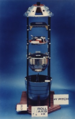 The specialized film return bucket used for the CORONA satellite. (CORONA film return bucker)


Wed Dec 22 21:30:19 EST 2010[edit]
errors[edit]
- File:American_satellite2.jpg verification-error
-
 Image of a declassified air force satellite.
 -
 Space station orbiting above earth
 -
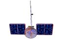 A rendering of an american satellite.
 -
An artist's impression of an american satellite orbiting earth.
-
 An artist's impression of an american satellite orbiting earth.
 -
 Picture of Jupiter and 2 of its moons.
 -
 An image of Ollie on the NRO JR logo. Back Cover for "What is a Satellite" book.
 -
 An image of Ollie from NRO JR for the front cover of the "What is a Satellite" book.
 -
 An artist's impression of an american astronaut on the moon with an orbting capsule.


Sat Dec 18 15:08:28 EST 2010[edit]
-
 Bar graph for the type of health insurance coverage (percentage) in 2008/2009 in the United States. (p25)
 -
 Bar graph of the Demographic Makeup of the Population at Varying Degrees of Poverty in the United States 2009. 18 or younger , 18-64, 65 and older (p19)
 -
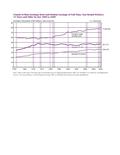 United States Female-to-Male Earnings Ratio and Median Earnings of Full-Time, Year-Round Workers 15 Years and Older by Sex: 1960 to 2009 in USD. (p11)
 -
 The Number of Uninsured americans and the Uninsured Rate from 1987 to 2009 in the United States. (p24)
 -
 Number of Americans in Poverty and the Poverty Rate in the United States from 1959 to 2009. (p14)
 -
 Poverty Rates by Age in the United States from 1959 to 2009. (p17)
 -
 The median household income by race and Hispanic Origin in the United States from 1967 to 2009. (p6)
 -
 The total and full-time, year-Round Workers With Earnings by gender in the United States from 1967 to 2009. (p13)
 -
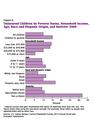 The uninsured children by poverty Status, Household Income, Age, Race and Hispanic Origin, and Nativity in the United States in 2009.Bar graph. (p28)
Mon Dec 06 10:46:34 EST 2010[edit]


Sun Sep 26 13:40:08 EDT 2010[edit]
-
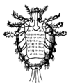
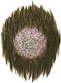
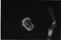
 Acarus scabiei. Female, ventral surface 75x
 -
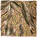
 Primula obconica(P. poculifornis)
_Acarus_scabiei._Female,_ventral_surface_75x.png)
_Primula_obconica(P._poculifornis).jpg)
Sun Sep 26 13:36:24 EDT 2010[edit]
errors[edit]
- File:An_introduction_to_dermatology_(1905)_Acarus_scabiei._Female,_ventral_surface_75x.jpg verification-error
- File:An_introduction_to_dermatology_(1905)_Primula_obconica(P._poculifornis).png verification-error
-
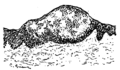
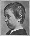
 ALOPECI AREATA
 -
Acarus scabiei. Female, ventral surface 75x
-
 Acitonomycosis
 -
 Acne (indurta)
 -
 Bromide Rash
 -
 Bullous eruption Septic Pemphigus
 -
 CHEIROPOMPHOLYX
 -
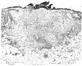 Figure 43. Catarrhal Lupus. Leucocytes are present in such amount as to completely conceal the tuberculous structure. Traces of epithelium covered the whole surface, and the overlying crust teemed with microcci. 50x
 -
 Craterifrom of growth of Tricopython megalosporon
 -
 Culture of Ringworm of the Beard
 -
 Dermatitis herpetiformis. Cover of vesicle is practically the entire eptthelial layer.In the vesicle are threads of coagulated fibrin and a few leucocytes.The vessels beneath are sheathed with exudation cells.
 -
 Dermographism
 -
 Diagram of Skin
 -
 Diagrams of the areas served by the nerve fibers passing through the several spinal root ganglia
 -
 ERYTHEMA IRIS
 -
 ERYTHEMA NODOSUM
 -
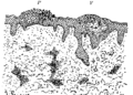 Eczema. The scaly spot, P, show parkeratosis, at V, a vesicle has formed in the prickle layer, whose cells show irregular cornification (parakeratosis and proliferation acanthosis). Deep changes are shown by the infilitration around the vessels. 50x
 -
 Erythema Bullosum
 -
 Erythema following vacination
 -
 Erythema multiforme showing dilated vessels, cellular infiltration around them, with some thickening of the horny layer. 50x
 -
 Favus
Favus -
 Favus
Favus -
 Figure 44. Fibroid Lupus. Dense connective tissue. The tuberculous areas contain numerous giant cells, and the surface epithelium is as usual increased in amount. 75x
 -
 Hydroa gravidarum
 -
 Hydroa vacciniforme
 -
 Ichtyosis
 -
 Ichtyosis
 -
 Fig 26. Ichtyosis diagram. Horny layer increased, rete thin, Alpine papillae, some cellularity of the corum 50x
 -
 Ichtyosis
 -
 Impetigo circinata
 -

-
 Lichen planus
 -
 Lichen planus
 -
 Longitudinal section of 12th dorsal ganglion. Death 103 days after eruption first appeared.
 -
 Longitudinal section of nail (diagrammatic)
 -
 Figure 47. Lupus erythematosus section shows the exceedingly thin epidermis and the dropsical corium packed with leucocyes and young connected tissue cells. 350x
 -
 Figure 46. Lupus erythematosus section. The corium is dropsical and packed with cells, masses of coagulated fibrin are shown at F and at H are seen the horny plugs which are evident clinically on the under surface of the scales, stained with acid orcein and haematoxylin. 50x
 -
 Lupus vulgaris
 -
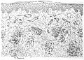 Figure 42. Lupus vulgaris simplex. The corium is studded with little collections of tuberculous follicles which make up the apple-jelly nodules. The vessles are dilated and the tissues between the nodules contain many leuocytes. Teh epithelium is slightly cedematous and the horny layer is irrefular. 75x
 -
 Miliaria. Section of double vesicle evidently devolpe din the prickle layer and evidently inflammatory. Leucocytes and epithelial cells in the cavity. After Unna. 80x
 -
 Figure 50. Molluscum Contagiosum section. Central section shows lobulated character,molluscum bodies, in the centers of the lobules and in this case, a central dimple. Sometimes this is replaced by a projection. 50x
 -
 Molluscum contagiosum on the Leg
 -
 Mycosis Fungoides (Jamieson's case) June 1902
 -
 Mycosis Fungoides (Jamieson's case) October 1902
 -
 Mycosis Fungoides later stage
 -
 Mycosis Fungoides
 -
 Ovum of the pediculus capitis or nit attached by a sheath to the hair 50x.
 -
 Figure 35. Part of a hair affected by Favus. Hair comes out entire, long filaments of fungus inside the shaft, a felt work of fungus in a portion of the sheath. Stained by Morris's method. 100x
 -
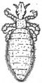
 Pediculus corporis 50x
 -
 Pediculus pubis 50x
 -
 Pemphigus
 -
 Pityriasis rosea
 -
 Fig. 31 Portion of Hair affected with large-spored or rosary variety of the fungus (Trichophyton megalosporon). Stained by Morris's method. 300x
 -
 Fig 29. Portion of Hair affected with small-spored or "mosaic" variety of fungus (Microsoporn Audouni). Stained by Morris's method. 300x
 -
 Portion of a Sebaceous Gland 300x
 -
Primula obconica(P. poculifornis)
-
 Psoriasis (partly treated)
 -
 Psoriasis
 -
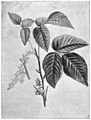 Rhus toxicodendron
 -
 Ringworm
 -
 Seborrhcea
 -
 Seborrhcea
 -
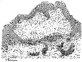
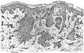 Figure 48. Section from rodent ulcer. The section is tekn from a part which was not ulcerated and show the typical collection of cells, some of which have a whorled arrangement. 50x
 -
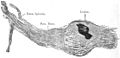
 Section froma case of Norwgian scabies(diagrammatic). Shows postion of the itch mite, the eggs in the oblique burrow, and in other parts of the horny layer, section of acari and facial masses (the black granules). There is some cellular infiltration of the tissues beneath.
 -
 Figure 41-Section of a Lichen planus papule. Horny layer thickened, epidermis thickened and its cells enlarged and lengthened laterally. Dense growth of connective tissue cells in the corium, sharply magnified beneath. 75x
 -
 Figure 37. Section of a scutulum in situ, very thin layer of epidermis beneath, thin horny layer above. The fungus in the center is more closely packed, hence the depression. 100x
 -
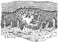
 Transverse section of Epidermis with Papilla cut across
 -
 Vessicle in the prickle layer, the epithelial cells pushed aside, and a few leucocytes in the cavity. 50x From a section by Windlereid William.
 -
 blastomycosis
 -
 comedo expressor
 -

-
 eczema 2
 -
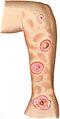
 very extensive case of Alopecia Areata Duration one year
 -
 erythema induratum
 -
 erythema induratum
 -
 fine fibrils of the Epithelial Cells (after Kromayer) 800x
 -
 herpes zoster
 -
 herpes zoster. large loculated vesicle,L,and a smaller single one,S. Both contain threads of fibrin, and a few leucocytes.Note the position in the prickle layer,and the infiltration around the vessels in the corium.
 -
 herpes zoster
 -
 keloid
 -
 kerion
 -
 lupus erythematosus
 -
 lupus erythematosus
 -
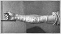
 maculo-anaesthetic leprosy
 -
 molluscum fibrosum 1
 -
 nodular leprosy
 -
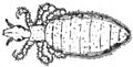
 pediculus capitis 42x
 -
 Fig 25. pityriasis rosea diagram. A little increase of the cellular layer of the epidermis, no granular layer. This increased horny layer which was closely adherent was detacched in preperation. A few leucocytes in the corum. 50x
 -
 ringworm
 -
 rodent ulcer
 -
 scabies
 -
 scleroderma
 -
 Fig 27. section of early lesion. The orifice of the gland is plugged by closely-packed layer of horny matter-the comedo. All sebaceous structure is gone and the gland is lined by horny layer. Some softer material in the centre has dropped out in preperation. 50x
 -
 showing moist dermatitis and one or two scutula
 -
 shows the vesicle to consist merely of a distension of the horny layer. At the lower right-hand corner of the vesicle is a port of a sweat duct. After Unna. 50x
 -
 syphilis (secondary)
 -
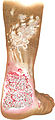 syphilis (tertiary)
 -
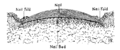 transverse section of nail
 -

-
 vitiligo or leucoderma
 -
 xanthoma diabetacorum
_ALOPECI_AREATA.jpg)
_Acitonomycosis.jpg)
_Acne_(indurta).jpg)
_Bromide_Rash.jpg)
_Bullous_eruption_Septic_Pemphigus.jpg)
_CHEIROPOMPHOLYX.jpg)
_Catarrhal_Lupus.jpg)
_Dermatitis_herpetiformis.png)
_Dermographism.jpg)
_Diagram_of_Skin.jpg)
_Diagrams_of_the_areas_served_by_the_nerve_fibers_passing_through_the_several_spinal_root_ganglia.png)
_ERYTHEMA_IRIS.jpg)
_ERYTHEMA_NODOSUM.jpg)
_Eczema.png)
_Erythema_Bullosum.jpg)
_Erythema_following_vacination.jpg)
_Erythema_multiforme_showing_dilated_vessels_50x.jpg)
_Favus_2.jpg)
_Favus.jpg)
_Fibroid_Lupus.jpg)
_Hydroa_gravidarum.jpg)
_Hydroa_vacciniforme.jpg)
_Ichtyosis_3.jpg)
_Ichtyosis_diagram.jpg)
_Ichtyosis.jpg)
_Impetigo_circinata.jpg)
_Impetigo_contagioso.jpg)
_Lichen_planus_1.jpg)
_Lichen_planus_2.jpg)
_Longitudinal_section_of_12th_dorsal_ganglion.jpg)
_Longitudinal_section_of_nail_(diagrammatic).png)
_Lupus_erythematosus_section_shows_the_exceedingly_thin_epidermis.jpg)
_Lupus_erythematosus_section.jpg)
_Lupus_vulgaris_2.jpg)
_Lupus_vulgaris_simplex.jpg)
_Miliaria_80x.png)
_Molluscum_Contagiosum_section.png)
_Molluscum_contagiosum_on_the_Leg.jpg)
_Mycosis_Fungoides_(Jamieson%27s_case)_June_1902.jpg)
_Mycosis_Fungoides_(Jamieson%27s_case)_October_1902.jpg)
_Mycosis_Fungoides_later_stage.jpg)
_Mycosis_Fungoides.jpg)
_Ovum_of_the_pediculus_capitis_or_nit_attached_by_a_sheath_to_the_hair_50x.png)
_Pediculus_corporis_50x.jpg)
_Pediculus_pubis_50x.png)
_Pemphigus.jpg)
_Pityriasis_rosea.jpg)
_Portion_of_a_Sebaceous_Gland_300x.jpg)
_Psoriasis_(partly_treated).jpg)
_Psoriasis.jpg)
_Rhus_toxicodendron.jpg)
_Ringworm.jpg)
_Seborrhcea_2.jpg)
_Seborrhcea.jpg)
_Section_from_rodent_ulcer.jpg)
_Section_from_a_case_of_Norwgian_scabies(diagrammatic).jpg)
_Section_of_a_Lichen_planus_papule_75x.jpg)
_Section_of_a_scutulum_in_situ.jpg)
_Transverse_section_of_Epidermis_with_Papilla_cut_across.jpg)
_Vessicle_in_the_prickle_layer.jpg)
_blastomycosis.jpg)
_ecthyma.jpg)
_very_extensive_case_of_Alopecia_Areata_Duration_one_year.jpg)
_erythema_induratum_2.jpg)
_erythema_induratum.jpg)
_fine_fibrils_of_the_Epithelial_Cells_(after_Kromayer)_800x.jpg)
_herpes_zoster_2.jpg)
_herpes_zoster_3.jpg)
_herpes_zoster.jpg)
_keloid.jpg)
_kerion.jpg)
_lupus_erythematosus_2.jpg)
_lupus_erythematosus.jpg)
_maculo-anaesthetic_leprosy.jpg)
_molluscum_fibrosum_1.jpg)
_nodular_leprosy.jpg)
_pediculus_capitis_42x.jpg)
_pityriasis_rosea_diagram.png)
_ringworm_photo.jpg)
_rodent_ulcer.jpg)
_scabies.jpg)
_scleroderma.jpg)
_section_of_early_lesion.png)
_showing_moist_dermatitis_and_one_or_two_scutula.jpg)
_shows_the_vesicle_to_consist_merely_of_a_distension_of_the_horny_layer.png)
_syphilis_(secondary).jpg)
_syphilis_(tertiary).jpg)
_transverse_section_of_nail.png)
_tuberculosis_fig._45.jpg)
_vitiligo_or_leucoderma.jpg)
Sat Sep 25 15:28:17 EDT 2010[edit]
-
 Lupus vulgaris

Sat Sep 25 15:27:28 EDT 2010[edit]
errors[edit]
- File:Lupus_vulgaris.jpg aborted
- File:Tricopythosis_capitis1.jpg verification-error
-
 Dermatatis Calorica
 -
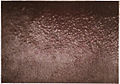 Dermatatis Venentana
 -
 Dermatitis exfoliativa
 -
 Keloid
 -
 Urticaria Pigmentoso
 -
 Urticaria
 -
 Varigecella
 -
 Acne vulgaris
 -
 Acne vulgaris
 -
 Alopecia areata
 -
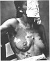 Chomophytosis
 -
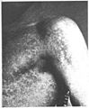 Chomophytosis
 -
 Cornua cutaneum
 -
 Eczema
 -
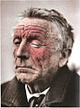 Eczema erythematosum
 -
 Eczema faciei
 -
 Eczema faciei
 -
 Eczema intertrigo
 -
 Eczema rubrum et squamosum
 -
 Eczema squamosum
 -
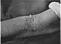 Eczema squamosum
 -
 Eczema squamosum
 -
 Elephantiasis
 -
 Elephantiasis
 -
 Epithelioma
 -
 Epithelioma
 -
 Erythema bullosum
 -
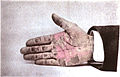 Erythema exofliativum
 -
 Erythema multiforme (herpes iris)
 -
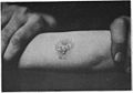 Favus capitis
 -
 Favus capitis
 -
 Fibroma
 -
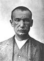 Herpes facilias
 -
 Ichthyosis
 -
 Ichthyosis
 -
 Keratosis follicularis
 -
 Lepra maculosa
 -
 Lepra maculosa
 -
 Leucoderma
 -
 Leucoderma
 -
 Lichen planus
 -
 Lichen planus
 -
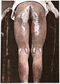 Lichen ruber
 -
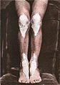 Lichen ruber
 -
 Lupus erythematosus
 -
 Lupus varrucosus
 -
 Lupus vulgaris
 -
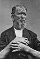 Neoplastic (not sure)
 -
 Neoplastic (not sure)
 -
 Permphigus
 -
 Phtheiriasis capitis
 -
 Phtheiriasis corporis
 -
 Porrigo (impetigo contagiosa)
 -
 Porrigo (impetigo contagiosa)
 -
 Psoriasis annulata
 -
 Psoriasis diffusa
 -
 Psoriasis guttata
 -
 Psoriasis manum
 -
 Psoriasis manum
 -
 Psoriasis nummalata
 -
 Pupura
 -
 Purpura
 -
 Rosacea
 -
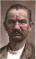 Rosacea
 -
 Rosacea
 -
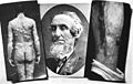 Sarcoma
 -
 Scabies
 -
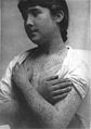 Scabies
 -
 Seborrhcea
 -
 Sycosis
 -
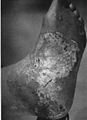 Syphiloderma squamosum
 -
 Tricopythosis
 -
Tricopythosis capitis
-
 Tricopythosis corporis
 -
 Tricopythosis crusis
 -
 Variola
 -
 Zoster frontalis
 -
 Zoster lumbo-femoralis


_1.jpg)


.jpg)
.jpg)


_1.jpg)
_2.jpg)


Tue Aug 24 08:21:42 EDT 2010[edit]
-
 Children finding Jack Ketch's knife which he used to kill Francis Beaumont.
 -
 An illustration of Jack Ketch's fictitous mother.
 -
 A fictitous illustration of Jack Ketch.
 -
 Misty in the parish.


Fri Aug 13 19:14:15 EDT 2010[edit]
-
 Figure 2-11. Mir base block. The multiport node at the station’s forward end (left) has one longitudinal docking port and four lateral berthing ports. The Mir space station is the centerpiece of the Russian manned space program. Its base block (figure 2-11) has been in orbit for 9 years.
 -
 Figure 2-12. The Mir complex as of June 1994, with docked Progress-M 23 (right) and Soyuz-TM 18 (left) spacecraft.
 -
 Figure 2-13. Altair/SR relay satellite. Mir was designed to be used with the Soviet Altair/SR geosynchronous voice and data relay satellites (figure 2-13). These are satellites operated under the ubiquitous Cosmos designation. The satellite system is sometimes designated SDRN (Satellite Data Relay Network) or Luch. A large antenna for radio communications with the Altair/SR system extends from the aft end of Mir.
 -
 Figure 2-14. Mir base block (left) and Kvant (right) (1987). Note third solar array added to the top of the Mir base block. It was delivered inside Kvant. Soyuz-TM and Progress vehicles omitted for clarity.
 -
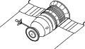 Figure 1-9. L1 (Zond) circumlunar spacecraft. The L1 (Zond) (figure 1-9) was meant to carry one or two cosmonauts on a circumlunar flight. It never flew manned, but did complete several unmanned circumlunar missions.
 -
 The L1 (Zond) (figure 1-9) was meant to carry one or two cosmonauts on a circumlunar flight. It never flew manned, but did complete several unmanned circumlunar missions.
 -
 Figure 2-16. Mir base block (center), Kvant (right), Kvant 2 (top), and Kristall (bottom) (1990). Note the EVA mooring post for YMK tests near Kvant 2’s EVA airlock hatch. It was added during a January 26, 1990 EVA. Soyuz-TM and Progress vehicles are omitted for clarity.
 -
 Figure 1-10. Proton configured for L1 (Zond). Note the modified Soyuz shroud (top).
 -
 Figure 2-17. Mir base block, Kvant, Kvant 2, and Kristall (1994). Note the Sofora boom and VDU and the Rapana girder attached to the top of Kvant, the Strela boom attached to the side of the base block, and the support on the side of the Kvant module. A matching support is attached to Kvant’s other side, out of view. Eventually Kristall’s two solar arrays will be relocated to these supports. Soyuz-TM and Progress spacecraft are omitted for clarity.
 -
 Figure 3-1. Station modules and tugs evolution. The chart above summarizes the evolution of vehicles originally developed as transport craft for the Almaz space station program and subsequently reapplied to many new functions. The narrow light gray arrow coming down from the top leads from the Soyuz Programs chart (figure 1-1). The broad gray arrows trace what is generally known in the West about the evolution of Soviet/Russian space station modules and tugs. The black-lined box encloses the TKS program, and the black arrows (solid and dashed) lead to the Station Programs chart (figure 2-1).
 -
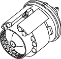 Figure 3-2. FGB. This is a simplified aft view of the propulsion/cargo module used in the TKS vehicles and as the basis for subsequent space station modules and tugs. Aft (left) details are conjectural. Solar arrays are omitted for clarity. The heritage of the space station modules joined to Mir is convoluted (figure 3-1). In all cases, however, they are based on a “universal block,” a vehicle referred to by the Russian acronym FGB (figure 3-2).
 -
 Figure 3-4. Merkur capsule.
 -
 Figure 3-3. TKS. The FGB and Merkur vehicles were joined together aft end to aft end to form a TKS; thus, this is a front view of the conical Merkur capsule (left), and an aft view of the FGB (right).
 -
 Figure 3-5. Cutaway of TKS vehicle. Details are conjectural. The broad black line outlines the vehicle’s pressurized compartments. A tunnel (stippled) connects the FGB and Merkur capsule.
 -
 Figure 1-11. L2 (Lunar Orbit Module). At the front of the spacecraft (left) is the Aktiv unit of the lunar mission Kontakt docking system. No L2 (figure 1-11) ever reached orbit. The spacecraft was meant to play the equivalent role of the U.S. manned lunar program’s Apollo CSM. An L2 is on display at the Moscow Aviation Institute.
 -
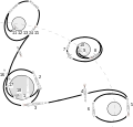 Figure 1-12. N-1/L3 lunar mission profile. 1. N-1 rocket liftoff. 2. LRS Earth orbit insertion. 3. LRS translunar injection using Block G rocket stage. Block G separates. 4. Midcourse correction using Block D rocket stage. 5. Lunar orbital insertion using Block D rocket stage. 6. Single cosmonaut transfers from L2 to L3 by EVA. 7. L3 lunar lander and Block D rocket stage separate from L2 Lunar Orbit Module. 8. Deorbit burn and powered descent using Block D rocket stage. Expended Block D rocket stage separates from the L3 1 to 3 km above the lunar surface. L3 continues powered descent using its own main or backup rocket motor. 9. L3 touchdown on Moon. 10. Expended Block D rocket stage crashes on Moon. 11. L3 liftoff using same engines used for final descent. Legs are left on Moon. 12. L2 rendezvous and docking with L3. 13. Cosmonaut transfers from L3 to L2 by EVA. L3 discarded. 14. Trans-Earth insertion burn using L2 main engine. 15. Midcourse correction using L2 main engine. 16. Orbital module and service module discarded. 17. Descent module reentry. 18. Parachute descent and touchdown on land.
 -
 Figure 3-6. Cosmos 1686. Note the Merkur capsule (left), heavily modified to house scientific instruments.
 -
 Figure 3-7. Cosmos 1686 and Salyut 7. Salyut 7/Cosmos 1686 complex (figure 3-7) massed 43 tons. Cosmos 1686 delivered 4500 kg of cargo, and nearly doubled the volume available to the Chegets. Unfortunately, they were little able to use the supplies and experimental apparatus or the room because of Vasyutin’s illness.
 -
 Figure 3-8. Kvant module. Kvant (figure 3-8) was originally designed for use with Salyut 7, but launch was delayed past the endurance of that station.
 -
 Figure 3-9. Kvant 2 module. Kvant 2 houses an EVA airlock (hatch visible at left). Referred to as D-module (Dushnashcheniye module) or augmentation module prior to launch (figure 3-9).
 -
 Figure 3-10. Lyappa arm. Modules for Mir’s lateral ports first dock at the front longitudinal port. Each module carries a Lyappa arm (top), which attaches to a socket (bottom) on the outside of the Mir multiport node. The arm then pivots the module to the proper lateral berthing port. Lyappa arm (figure 3-10) attached to a fixture in the Mir base block’s multiport docking node and pivoted Kvant 2 from the front longitudinal port to its assigned lateral port (figure 3-11). Kristall, Priroda, and Spektr also carry the Lyappa arm.
 -
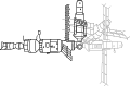 Figure 3-11. Repositioning Kvant module using Lyappa arm. Lyappa arm (figure 3-10) attached to a fixture in the Mir base block’s multiport docking node and pivoted Kvant 2 from the front longitudinal port to its assigned lateral port (figure 3-11). Kristall, Priroda, and Spektr also carry the Lyappa arm.
 -
 Figure 3-13. APAS-89 androgynous docking unit. At aft end is a node with two ports, each fitted with APAS-89 androgynous docking apparatus (figure 3-13). APAS-89 is similar to the APAS-75 docking unit (see section 1.9.2) jointly developed by the U.S. and Soviet Union for ASTP (1975).
 -
 Figure 3-12. Kristall module. Kristall joined Mir in 1990. It carries two APAS-89 docking units (left). Kristall (figure 3-12) referred to as the T-module (Teknologia module) or Kvant 3 prior to launch.
 -
 Figure 3-14. Kvant and FSM. The streamlined fairing covering the aft end of the FSM (right) pointed upwards at liftoff, and formed the nose of the launch stack. Probably the “purest” space tug of the Soviet/Russian program was the Kvant Functional Service Module (FSM) (figure 3-14). The FSM was a stripped-down FGB. Presumably it was thus launched “tail-up” like the TKS spacecraft, an idea supported by the streamlined structure covering the FSM’s aft, where the Merkur capsule would be located on a TKS. It was launched docked with Kvant’s aft port on March 31, 1987. This would have placed the Kvant module with the probe docking unit meant to attach it to Mir pointed downwards at launch, against the top of the Proton booster.
 -
 Figure 3-15. Polyus cutaway. Displays the FGB-based service/propulsion module. Note that, like other FGBbased vehicles, it launched aft end up. This places Polyus’ front end at the bottom. The streamlined projections on Polyus’ sides were dispensers for experimental tracking targets. In July-August 1992, Yu. P. Kornilov, chief lead designer at Salyut Design Bureau, described in an article the Polyus spacecraft (figure 3-15).17 Polyus (“pole of the Earth”) was the payload of the first Energia rocket flight (May 15, 1987) (figure 3-16). In July 1985, the Ministry of General Machine Building ordered the Salyut Design Bureau to create a new spacecraft for the first Energia test flight, then scheduled for autumn 1986. The short lead time forced novel approaches to management and construction. Existing hardware, including systems developed for the Buran shuttle program, was used whenever possible.
 -
 Figure 3-16. Polyus satellite on Energia launch vehicle. In July-August 1992, Yu. P. Kornilov, chief lead designer at Salyut Design Bureau, described in an article the Polyus spacecraft (figure 3-15).17 Polyus (“pole of the Earth”) was the payload of the first Energia rocket flight (May 15, 1987) (figure 3-16). In July 1985, the Ministry of General Machine Building ordered the Salyut Design Bureau to create a new spacecraft for the first Energia test flight, then scheduled for autumn 1986. The short lead time forced novel approaches to management and construction. Existing hardware, including systems developed for the Buran shuttle program, was used whenever possible.
 -
 Figure 1-14. Lunar rocket system. Consisted of (bottom to top) the Block G and Block D rocket stages, the L3 lander, and the L2 command ship. Launched atop an N-1 rocket with a L3 lunar lander and the Block G and Block D rocket stages. Together they formed the lunar rocket system (LRS) (figure 1-14).
 -
 Figure 1-13. N-1 rocket configured for lunar flight. The basic rocket consisted of the Block A first stage, the Block B second stage, and the Block V third stage. All stages burned liquid oxygen and kerosene. For lunar missions the LRS was added. The N-1 would have delivered about 100,000 kg to low-Earth orbit. (For a comparison with the U.S. Saturn V rocket, see figure 4-1). Flight-test version, dubbed T1K, was to have been launched on a Proton rocket. However, the T1K flight-test program was cancelled in favor of all-up testing on the N-1 rocket (figure 1-13).40 Similarly, in 1965, the Apollo program opted for unmanned allup testing.
 -
 N-1 (drawn to scale) manned moon rockets.
 -
 Figure 4-1. Saturn V (left) and N-1 (drawn to scale). Manned Moon rockets.
 -
 Saturn V rocket
 -
 LM Manned Moon lander
 -
 Figure 4-2. L3 (left) and Apollo LM (drawn to scale). Manned Moon landers.
 -
 L3 Manned Moon Lander
 -
 Figure 4-3. Apollo CSM (top) and L2 (drawn to scale). Command ships for the Moon voyage.
 -
 Apollo CSM command ship for moon voyage
 -
 L2 command ship for moon voyage
 -
 Figure 1-15. Kontakt docking system. Never used in space, the system was designed for the Soviet lunar program. The Aktiv unit (top) was located at the front of the L2, while the passive unit was located on top of the L3 lander. Carried a spring-loaded probe docking system, called Aktiv (“active”), which was designed to penetrate and grip a “honeycomb” drogue docking fixture on the L3. Together they were called Kontakt (figure 1-15). The docking system was to be used only once during the mission, after the L3 had completed its lunar landing mission and returned to orbit. Little docking accuracy was required to link the spacecraft firmly enough to let the moonwalking cosmonaut return to the L2 by EVA.
 -
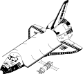 Figure 4-4. Space Shuttle Orbiter and Soyuz-TM (drawn to scale). Current spacecraft used by humans to travel in space
 -
 Space Shuttle Orbiter
 -
 Soyuz-TM
 -
 Energia-Buran
 -
 Figure 4-5. Soyuz rocket (left), Space Shuttle (center), and Energia-Buran (right) (drawn to scale). Rockets currently used to launch manned spacecraft into orbit.
 -
 Soyuz rocket
 -
 Space Shuttle
 -
 Figure 1-16. L3 lunar lander. The flat, downward-facing face (left) of the ovoid pressure cabin holds the round viewport (not visible). The Kontakt system passive unit is at cabin top, and two landing radar booms extend at left and right. Nozzles of two solid-fueled hold-down rockets are visible at the tops of the legs, near the bases of the radar booms.
 -
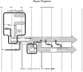 Figure 1-1. Soyuz evolution. The light gray arrows trace the evolution of flown spacecraft. The dark gray arrows show influence of concepts and flown spacecraft on other concepts and flown spacecraft. Broad black lines enclose distinct programs. The stippled and light gray arrows pointing downward, off the chart, connect to the Space Station chart (figure 2-1) and the Station Modules and Tug Programs chart (figure 3-1), respectively.
 -
 L3 ascent Left only its landing legs, landing radar, and a few other components behind on the Moon. Unlike the Apollo LM, which used separate descent and ascent propulsion systems, the L3 used the same main propulsion system for final descent and ascent. At liftoff from the lunar surface both the main and backup propulsion systems were activated. If both systems were found to be operating normally, the backup system was then shut down
 -
 Figure 1-18. Salyut 1-type Soyuz. This was the Original Soyuz upgraded for Salyut space stations. The probe and drogue docking system (left) permitted internal transfer of cosmonauts from the Soyuz to the station.
 -
 Figure 1-19. Soyuz internal transfer docking unit. This system is used today for docking spacecraft to Mir. The active craft inserts its probe into the space station receiving cone. The probe tip catches on latches in the socket at the apex of the cone. Motors then draw the two spacecraft together. Latches in the docking collars catch, and motors close them. Fluid, gas, and electrical connections are established through the collars. After the cosmonauts are certain the seal is airtight, they remove the probe and drogue units, forming a tunnel between spacecraft and station. At undocking, four spring push rods drive the spacecraft apart. If the latches fail to retract, the spacecraft can fire pyrotechnic bolts to detach from the station.
 -
 Figure 1-20. Soyuz Ferry. The Soyuz Ferry (figure 1-20) replaced the Salyut 1-type Soyuz. It transported crews of two cosmonauts to Salyut 3, Salyut 4, Salyut 5, and Salyut 6.
 -
 Figure 1-2. L1 Soyuz manned circumlunar concept (1962). Should not be confused with the L1 (Zond) spacecraft (figure 1-9). The cone at the front (right) of the L1 Soyuz is an attitude control module; behind it are cylindrical orbital and descent modules, and a frustum-shaped service module. The round appendage (right) is a solar array, and the dish, a high-gain antenna. At the rear of the L1 are three booster modules.
 -
 Figure 1-21. Apollo-Soyuz Test Project (ASTP) Soyuz. The APAS-75 docking unit is located at left.
 -
 Figure 1-22. APAS-75 docking unit. Unlike previous docking systems, both units could assume the active or passive roles as required. For docking, the spade-shaped guides of the extended active unit (right) and the retracted passive unit (left) interacted for gross alignment. The ring holding the guides shifted to align the active unit latches with the passive unit catches. After these caught, shock absorbers dissipated residual impact energy in the American unit; mechanical attenuators served the same function on the the Soviet side. The active unit then retracted to bring the docking collars together. Guides and sockets in the docking collars completed alignment. Four spring push rods drove the spacecraft apart at undocking. The passive craft could play a modified active role in undocking if the active craft could not complete the standard undocking procedure. Pyrotechnic bolts provided backup.
 -
 Figure 1-23. Apollo and Soyuz join in space. Note the docking module (DM) attached to Apollo’s nose. The DM was stored for launch within a shroud between the CSM and the S-IVB second stage of the Apollo Saturn IB launch vehicle. In orbit the Apollo inserted its probe unit into the standard Apollo drogue unit of the docking module, extracted the DM from the S-IVB, then performed rendezvous and docking with the Soyuz spacecraft.
 -
 Figure 1-24. Progress logistics resupply spacecraft. It consists of the dry cargo module (left); the tanker compartment (center); and a stretched service module (right). Progress (figure 1-24) was an unmanned version of the Soyuz Ferry designed to perform logistics resupply of the Salyut 6, Salyut 7, and Mir space stations. Progress missions 1 through 12 carried supplies to Salyut 6. Missions 13 through 24 visited Salyut 7, as did the unusual Progress-related Cosmos 1669 mission. Progress missions 25 through 42 served the Mir station. The first 17 Progress missions to Mir delivered 40 tons of supplies, about double the station’s launch weight. Most Progress spacecraft functioned routinely, as expected of a logistics spacecraft. No docking anomalies occurred in the 43 flights of Progress (Progress 1 through 42 plus Cosmos 1669).
 -
 Figure 1-4. Soyuz-A manned spacecraft concept (1963). It was to have been part of the Soyuz A-B-C circumlunar complex
 -
 Figure 1-3. Vostok rocket. This is a two-and-a-half-stage derivative of the one-and-ahalf- stage rocket which launched Sputnik 1 (1957). Its original ancestor was the SS-6 “Sapwood” ICBM. It served as the basis for the Soyuz launcher (figure 1-7), in service today. Weight of payload launched to 200-km, 51° circular orbit is 4730 kg.
 -
 Figure 1-25. Progress-based Gamma astrophysical research satellite. Mir space station modules are based on TKS transport vehicles originally designed for the Almaz military space station program (see Part 3, “Space Station Modules,” and section 2.1.2). Prior to the decision to convert the TKS into space station modules, work was underway to develop Progress-derived space station modules for Mir. The first, Gamma, was launched on July 11, 1990. It flew as an independent astrophysical research satellite (figure 1-25); it was not intended to dock with a space station. The docking system which would have made it part of a multimodular space station was replaced by a housing for two telescopes in the flown version. Gamma weighed 7.32 tons, and carried 1.7 tons of scientific gear. The Gamma-1 gamma-ray telescope alone weighed 1.5 tons. The spacecraft carried solar arrays with a total area of 36.5 m2, providing maximum power of 3.5 kW. The arrays, unlike those of Progress and Soyuz, were driven by electric motors to maintain their lock on the Sun. It was intentionally deorbited at the end of its mission. No module of this type has ever docked with Mir, though modules with similar designs have appeared in drawings of Mir’s proposed successor, Mir 2.
 -
 Figure 1-27. Ballistic return capsule (Raduga) during final descent to Earth. Return payload capability when equipped with Raduga (“rainbow”) ballistic return capsule (figure 1-27). The Russians use this capsule to return small, valuable payloads from Mir. It was named Raduga largely for marketing purposes. The capsule is carried in the Progress-M dry cargo compartment. At the beginning of Raduga’s return to Earth, the Progress-M completes its deorbit burn. At an altitude of about 120 km, the capsule separates.
 -
 Figure 1-26. Progress-M logistics resupply spacecraft. Progress-M (figure 1-26) is the Progress logistics resupply spacecraft upgraded by incorporating Soyuz-TM technology and other improvements.
 -
 Figure 1-28. Soyuz-T spacecraft. Soyuz-T (figure 1-28) replaced Soyuz Ferry. The “T” stands for transport. Soyuz-T gave the Soviets the ability to launch three cosmonauts in a single spacecraft for the first time since Soyuz 11 in 1971. It was used with the Salyut 6, Salyut 7, and Mir stations.
 -
 Figure 1-5. Soyuz A-B-C circumlunar concept. The drawing shows Soyuz-A (right), Soyuz-B booster, and Soyuz-C tanker with twin whip antennae (left).
 -
 Figure 1-29. Soyuz launch pad abort sequence. The modules of the Soyuz spacecraft are shown beneath the launch shroud by dashed lines. Note the separation plane between the Soyuz descent and service modules.
 -
 Figure 1-30. Soyuz-TM spacecraft. Compare the antennae on the orbital module to those on Soyuz-T. Differences reflect the change from the Igla rendezvous system used on Soyuz-T to the Kurs rendezvous system used on Soyuz-TM.
 -
 Figure 2-1 is a space station family tree Figure 2-1. Station evolution. The chart above summarizes the development of the Soviet/Russian space stations and derivatives. Light gray arrows trace the evolution of space stations and satellites derived from space station hardware. Dark gray arrows trace the influence of concepts on later flown hardware. The stippled arrow leads from the Soyuz Programs chart (figure 1-1). Solid black arrows indicate modules joined to Mir, while dashed black arrows stand for modules to be added to Mir in the near future. These arrows lead from the Station Modules and Tug Programs chart (figure 3-1).
 -
 Figure 2-2. Conceptual drawing of Siber multimodule space station and Siber ferry (1962). The space station concept is very old in Russia. Space pioneer Konstantin Tsiolkovskii wrote about space stations as early as 1903.1 The first space station event relevant to this discussion occurred in March 1962, when Sergei Korolev’s OKB-1 design bureau (ancestor of RKK Energia–until recently, NPO Energia) produced a report called “Complex for the Assembly of Space Vehicles in Artificial Earth Satellite Orbit (the Soyuz).” The report was largely concerned with assembly in Earth orbit of a vehicle for circumlunar flight, but also described a small station made up of independently launched modules. Three cosmonauts were to reach the station aboard a manned transport spacecraft called Siber (or Sever) (“north”), shown in figure 2-2. They would live in a habitation module and observe Earth from a “sciencepackage” module.
 -
 Figure 2-4. Partial cutaway of Proton configured for space station launch. The three-stage Proton rocket has launched all Soviet space stations and space station modules. Proton first flew as a two-stage vehicle in 1965. The threestage version used to launch stations debuted in 1969 and was declared operational in 1970. All three stages burn UDMH and N2O4 propellants. The three-stage Proton can place 20,000 kg in a circular 185 km orbit at 51.6° of inclination.
 -
 Figure 2-3. Salyut 1. Visible at the rear of the station (left) is the Soyuz-based propulsion module. A Salyut 1 Soyuz prepares to dock at the front of the station (right). Note the station’s Soyuz-type solar arrays.
 -
 Figure 2-5. Almaz radar satellite.
 -
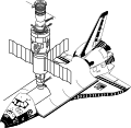 Conceptual drawing of Shuttle docked with Salyut. In October 1976, Acting NASA Administrator Alan Lovelace met with Intercosmos Council chairman Boris Petrov and other Soviet officials to discuss a Shuttle docking with a Salyut space station (figure 2-6). NASA would not commit to any program ahead of the approaching U.S. Presidential elections.
 -
 Figure 2-7. Salyut 3, the first successful Almaz space station. The drogue docking unit is at the rear of the station (left), between the two main engines.
 -
 Figure 2-8. Salyut 4, the second DOS station to be manned. Structural layout very similar to that of Salyut 1. That is, it had a single docking port leading into a transfer compartment, a work compartment divided into smalldiameter and large-diameter sections, and a propulsion and service module based on the Soyuz service module (figure 2-8). It was the last of four DOS-type stations based on hulls from the Almaz program.
 -
 Figure 1-6. Original Soyuz spacecraft. The three-seater Original Soyuz (figure 1-6) was the first ancestor of the Soyuz-derived vehicles in use today. The Original Soyuz played much the same role in the Soviet manned lunar program as Gemini did in the U.S. manned lunar program. That is, it provided experience in essential techniques and technologies for lunar flight.
 -
 Figure 1-7. Soyuz rocket. With more than 1000 launches to its credit since 1963, the two-and-a-half-stage Soyuz rocket has flown more than any other. Propellants are liquid oxygen and kerosene. Weight of payload launched to 200-km, 51° circular orbit is 7000 kg.
 -
 Figure 1-8. Original Soyuz probe and drogue docking system. The active unit (right) consisted of a probe and latches; the passive unit, a receiving cone, socket, and catches. The passive unit’s frustum was longer than the active unit’s because it was designed to accept the probe. The probe acted as a shock absorber. Its tip contained sensors which registered contact with the cone, disabled the active craft’s control system, and fired thrusters on the active craft to force the spacecraft together. The probe entered the socket at the apex of the cone, whereupon catches and a restraining ring locked it into place. Plugs and sockets in the rims of the docking units then established electrical and intercom connections between the spacecraft.


_and_Kvant_(right)_(1987).svg)
_circumlunar_spacecraft.svg)
,_Kvant,_and_Kvant_2_(top)_(1989).svg)
,_Kvant_(right),_Kvant_2_(top),_and_Kristall_(bottom)_(1990).svg)
.svg)


.svg)


_and_N-1_(drawn_to_scale).svg)

_and_Apollo_LM_(drawn_to_scale).svg)

_and_L2_(drawn_to_scale).svg)


.svg)


,_Space_Shuttle_(center),_and_Energia-Buran_(right)_(drawn_to_scale).svg)


.svg)
_Soyuz.svg)


.svg)

_during_final_descent_to_Earth.svg)


.svg)


Sun Jul 25 15:08:41 EDT 2010[edit]
-
 A viking ship on a book cover.
 -
 "Beowulf was eager for the contest, so taking with him fifteen warriors and good comrades, he stepped into a ship and bade the captain set sail for Daneland. Then like a bird wind-driven upon the waves, the foam-necked ship sped forth. For two days the warriors fared on over the blue sea, until they came again to Daneland and anchored beneath the steep mountains of that far shore." An illustration of Beowulf sailing to Daneland. Title illustration
 -
 A black and white illustration of a mother and son reading a book on a chair.
 -
 "Very terrible was this ogre Grendel to look upon. Thick black hair hung about his face, and his teeth were long and sharp, like the tusks of an animal. His huge body and great hairy arms had the strength of ten men. He wore no armour, for his skin was tougher than any coat of mail that man or giant might weld. His nails were like steel and sharper than daggers, and by his side there hung a great pouch in which he carried off those whom he was ready to devour. Now day by day this fearsome giant was tortured more and more, for to him it was a torture to hear the sounds of laughter and of merriment. Day by day the music of harp and song of minstrel made him more and more mad with jealous hate." An illustration of the ogre Grendel from Beowulf. *Marshall, Henrietta Elizabeth (1908) Stories of Beowulf, T.C. & E.C. Jack, p. 5 *Stories of Beowulf-1 Page 024 Image 0002.jpg
 -
 "Then forth from the bower came Wealtheow, Hrothgar's queen. Stately and tall, and very beautiful she came, clothed in rich garments girdled with gold. A golden crown was upon her head, and jewels glittered upon her neck. In her hand she held a great golden cup. set with gems. First to King Hrothgar she went and gave to him the beaker. 'Hail to thee,' she cried, 'mayest thou have joy of the drinking, joy of the feast, ever dear to thy people.' And Hrothgar drank, merry of heart, glad with thoughts of the morrow. Then through all the Hall Wealtheow moved, speaking gracious words, giving to each warrior, young and old, wine from the golden cup. At last she, the crowned queen, courteous and beautiful, came to Beowulf. Graciously Wealtheow smiled upon the Goth lord, holding the beaker to him. ' I thank the Lord of All, that thou art come to us,' she said. 'Thou art come, noble earl, to bring us comfort, and to deliver us out of our sorrows.' The fierce warrior bowed before the beautiful queen, as he held the wine-cup. He felt the joy of battle rise within him, and aloud he spake: ' I sware it when I did set out upon the deep sea, as I stood by my comrades upon the ship. I sware that I alone would do the deed or go down to death in the grip of the monster. As an earl I must fulfil my word, or here in the Hart Hall must I await my death-day.'" An illustration in Beowulf of the queen pouring wine for the warrior. *Marshall, Henrietta Elizabeth (1908) Stories of Beowulf, T.C. & E.C. Jack, p. 29 *Stories of Beowulf-1 Page 050 Image 0002.jpg
 -
 "Then in wrath Beowulf threw the shining blade upon the ground. He would trust no more in weapons but with his hands alone would he fight. Seizing the Water Witch by the shoulders, he dragged her downwards. But she grappled with him fiercely. Then was there a fearful fight in that dim hall, deep under the water, far from all hope of help. Back and forth the two swayed, the strong warrior in armour and the direful Water Witch. So strong was she that at last she bore him to the ground and kneeled upon his breast. She drew her dagger. Now she would avenge her son, her only son. The dagger shone and fell again and yet again. And then truly Beowulf's last hour had come had his armour not been of such trusty steel. But through it neither point nor edge of dagger might pierce. The blows of the Water Witch were all in vain, and again Beowulf sprang to his feet." An illustration of the water witch trying to stab Beowulf. *Marshall, Henrietta Elizabeth (1908) Stories of Beowulf, T.C. & E.C. Jack, p. 59 * Stories of Beowulf-1 Page 082 Image 0002.jpg
 -
 "His eyes were dazzled by the shining heap. Upon it lay a cup of gold, wondrously chased and adorned. 'If I can but gain that cup,' said the slave to himself, ' I will return with it to my master, and for the sake of the gold he will surely forgive me.' So while the Dragon slept, trembling and fearful the slave crept nearer and nearer to the glittering mass. When he came quite near he reached forth his hand and seized the cup. Then with it he fled back to his master. It befell then as the slave had foreseen. For the sake of the wondrous cup his misdeeds were forgiven him. But when the Dragon awoke his fury was great. Well knew he that mortal man had trod his cave and stolen of his hoard." An illustration of the slave in Beowulf who stole the dragon's golden cup, thinking to redeem himself, and thus aworke the dragon. *Marshall, Henrietta Elizabeth (1908) Stories of Beowulf, T.C. & E.C. Jack, p. 93 *Stories of Beowulf-1 Page 108 Image 0002.jpg
 -
 "Now he belched forth flaming fire." An illustration of Beowulf fighting the dragon that appears at the end of the epic poem. *Marshall, Henrietta Elizabeth (1908) Stories of Beowulf, T.C. & E.C. Jack, p. 93 *Stories of Beowulf-1 Page 122 Image 0002.jpg
 -
 "They carried with them the hideous head of Grendel." An illustration of 4 men carrying the head of Grendel. *Marshall, Henrietta Elizabeth (1908) Stories of Beowulf, T.C. & E.C. Jack, p. 63 *Stories of Beowulf-88.jpg


Sun Jul 25 13:59:55 EDT 2010[edit]
-
 "He knew his days upon this earth were past" Wiglaf speaking to Beowulf after his battle with the dragon. Beowulf is mortally wounded. Marshall, Henrietta Elizabeth (1908) Stories of Beowulf, T.C. & E.C. Jack, p. 99

Sun Jul 25 13:59:07 EDT 2010[edit]
errors[edit]
- File:Stories_of_beowulf_wiglaf_and_beowulf verification-error
-
"He knew his days upon this earth were past" Wiglaf speaking to Beowulf after his battle with the dragon. Beowulf is mortally wounded. Marshall, Henrietta Elizabeth (1908) Stories of Beowulf, T.C. & E.C. Jack, p. 99
Fri Feb 12 21:51:38 EST 2010[edit]
-
 The cover page for Solar Dynamics Observatory (SDO) A Guide to the Mission and Purpose of NASA’s Solar Dynamics Observatory It illustrates SDO looking at the sun.
 -
 Solar storm impacting Earth and its magnetic shield.
 -
 Solar storm shooting into space.
 -
 Magnetic activity on the surface of the Sun.
 -
 The Sun, as observed by STEREO, in four wavelengths of extreme UV light and taken at nearly the same time. SDO will take images in 10 wavelengths every 10 seconds.
 -
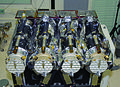 The AIA instrument as it is being assembled. It is like an IMAX® camera for the Sun.
 -
 This is the completed EVE instrument. It will have the highest time resolution (10 seconds) and the highest spectral resolution (better than 0.1 nm) ever achieved by a space-based solar observatory.
 -
 The HMI instrument gets a close look as it is being assembled. Helioseismic and Magnetic Imager (HMI)
 -
 Magnetogram (magnetic image) of the Sun showing magnetically intense areas (active regions) in black and white.
 -
 Looping arcs of particles spiraling along magnetic field lines rising up from beneath the surface and back into the Sun.
 -
 SDO will study the solar interior. A picture of the sun and its interior.
 -
 SDO’s images are super HD A picture of how the SDO will show the sun.
 -
 SDO’s images are super HD A picture of how the SDO will show the sun.
 -
 A powerful solar flare erupts as observed in extreme UV light. 2003-10-28
 -
 The SDO spacecraft getting a final checkout before heading to Cape Canaveral for launch.
 -
 Living with a star logo/illustration.
 -
 A very dynamic Sun (left) compared to a Sun deep in solar minimum (right) helps to illustrate the extremes of a solar cycle. Measured in UV light. 2000/2009
 -
 Illustration of convoluted magnetic field lines extending out all over the Sun.
 -
 Measurements from the SORCE mission indicate that the variability of total solar irradiance has decreased over the past six years.
 -
 SDO will be able to detect helioseismic waves inside the Sun.
 -
 In early photography, high-cadence images revealed details of motion more than the human eye could see
 -
 SDO will beam back 150 million bits of data every second A trail of green 0's and 1's (binary).
 -
 One of two large radio antennas that serve as SDO’s dedicated ground station near Las Cruces, NM.
 -
 Illustration of the SDO spacecraft keeping a watchful eye on the Sun, all day, every day.
 -
 Milestones of solar exploration and the Monthly Sunspot Number since 1750.
 -
 A solar storm blasts particles and magnetic field out into space from an active region on the Sun.
 -
 A coronal hole in extreme UV light.
 -
 In this coronagraph, the white circle represents the size of the Sun.
 -
 A coronal mass ejection. 2003-10-28
 -
 Granules on the Sun’s surface, with each about the size of Texas.
 -
 A large solar prominence on the sun.
 -
 Magnetic loops on the sun's surface.
 -
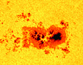 Close-up of a sunspot group on the sun.


Fri Feb 12 20:18:10 EST 2010[edit]
-
 A dynamic sun with numerous active regions seen in extreme UV light in July 2000 (SOHO)
 -
 SDO being assembled in the clean room at Goddard.


Wed Sep 02 18:37:47 EDT 2009[edit]
errors[edit]
- File:Bold_icon.png UnexpectedAnswerException unexpected response data (UiSimpleActionBase) status HTTP/1.0 200 OK
- File:Bouton_Vandale0.png UnexpectedAnswerException unexpected response data (UiSimpleActionBase) status HTTP/1.0 200 OK
- File:Button_Tool_commons.png UnexpectedAnswerException unexpected response data (UiSimpleActionBase) status HTTP/1.0 200 OK
-

-
 lossless compression
 -
 lossless compression...testing


_Acarus_scabiei._Female,_ventral_surface_75x.jpg&action=edit&redlink=1)
_Primula_obconica(P._poculifornis).png&action=edit&redlink=1)
_Acarus_scabiei._Female,_ventral_surface_75x.jpg)
_Primula_obconica(P._poculifornis).png)
Wed Sep 02 18:36:31 EDT 2009[edit]
errors[edit]
- File:Bold_icon.png UnexpectedAnswerException unexpected response data (UiSimpleActionBase) status HTTP/1.0 200 OK
- File:Bouton_Vandale0.png UnexpectedAnswerException unexpected response data (UiSimpleActionBase) status HTTP/1.0 200 OK
-
-
lossless compression
Wed Sep 02 18:34:38 EDT 2009[edit]
errors[edit]
- File:Bold_icon.png UnexpectedAnswerException unexpected response data (UiSimpleActionBase) status HTTP/1.0 200 OK