File:CharlieplexedArray4.png

Original file (3,600 × 1,200 pixels, file size: 134 KB, MIME type: image/png)
Captions
Captions
Summary[edit]
| Description |
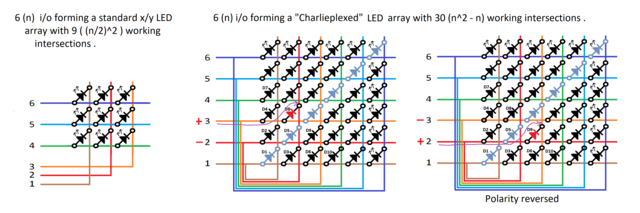
English: Unlike in a traditional x/y multiplexed array, where a sub-set of conductive elements crosses a different sub-set of conductive elements, in a "Fully Charlieplexed" multiplexed array, each conductive element crosses every other conductive element.
Six (n) conductive elements in a Standard x/y multiplexed array forms a maximum of nine ((n/2)²) unique intersections (see figure on left). The other diagrams also show six (n) conductive elements, but each element crosses every other element, forming a multiplexed array of 36 (n²) intersections. LEDs are shown placed at every intersection. However, each conductor also crosses itself at the diagonal. Horizontal conductor 1 crosses vertical conductor 1, horizontal conductor 2 crosses vertical conductor 2, etc. This means that six of these LEDs are short-circuited (e.g. D1 and D5 are short circuited). The 6 (n) diagonal (light blue here) LEDs will, therefore, never light up, because no voltage can ever develop across them, so (n) has to be subtracted from the total. There is no point in installing these LEDS (they are simply included here for illustrative purposes), but these light blue LEDs can be conveniently replaced by short-circuits (so that there's no need to setup the interconnections grouped on the left and the bottom of the diagram, to drive the vertical connectors in the array from the input of horizontal connectors). This leaves 30 (n² − n) LEDs in the matrix that can light up. Conductor "a" crossing conductor "b" is distinguishable from conductor "b" crossing conductor "a" because LED polarity is reversed. For example, when conductor 3 is positive and conductor 2 is negative, current flows through, and lights up LED D8, but when conductor 3 is negative and conductor 2 is positive, current flows through, and lights up LED D9. This allows all 30 (n² − n) LEDS to be uniquely addressed, and they can all be lit independently. These reverse polarity LED pairs are called complementary pairs. This diagram has 15 complementary pairs, allowing 30 LEDs to be lit independently. |
| Date | |
| Source | Own work |
| Author | Ron Binstead |
Licensing[edit]
- You are free:
- to share – to copy, distribute and transmit the work
- to remix – to adapt the work
- Under the following conditions:
- attribution – You must give appropriate credit, provide a link to the license, and indicate if changes were made. You may do so in any reasonable manner, but not in any way that suggests the licensor endorses you or your use.
- share alike – If you remix, transform, or build upon the material, you must distribute your contributions under the same or compatible license as the original.
File history
Click on a date/time to view the file as it appeared at that time.
| Date/Time | Thumbnail | Dimensions | User | Comment | |
|---|---|---|---|---|---|
| current | 19:04, 29 May 2023 | 3,600 × 1,200 (134 KB) | Touchscreen1 (talk | contribs) | Uploaded own work with UploadWizard |
You cannot overwrite this file.
File usage on Commons
There are no pages that use this file.
File usage on other wikis
The following other wikis use this file:
- Usage on en.wikipedia.org