Category:Wikiversity images
Jump to navigation
Jump to search
Subcategories
This category has the following 4 subcategories, out of 4 total.
Media in category "Wikiversity images"
The following 200 files are in this category, out of 481 total.
(previous page) (next page)-
 030 PM Project Preparation.png 2,000 × 1,014; 115 KB
-
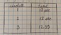
 03lists.jpg 320 × 236; 19 KB
-
 0416999-2-2-H.JPG 2,592 × 1,936; 2.03 MB
-
 1 pedido venta.png 587 × 468; 13 KB
-
 120 degree separation bar.JPG 1,600 × 1,200; 1.07 MB
-
 12Tapping copper nut.JPG 1,936 × 2,592; 1.59 MB
-
 2 dc motor.png 828 × 482; 76 KB
-
 20131029 110934h.jpg 640 × 480; 192 KB
-
 20131029 111832h.jpg 640 × 480; 184 KB
-
 20131031 094515h.jpg 640 × 480; 181 KB
-
 24 deg angle.jpg 1,536 × 2,048; 927 KB
-
 26 gauge mag.JPG 1,600 × 1,200; 493 KB
-
 26 Lead wire connection.JPG 1,600 × 1,200; 491 KB
-
 26A3.PNG 581 × 312; 11 KB
-
 26A50.PNG 636 × 307; 11 KB
-
 26A6.PNG 602 × 305; 11 KB
-
 26A9.PNG 634 × 308; 11 KB
-
 26Azoom.PNG 373 × 334; 9 KB
-
 26B3.PNG 729 × 367; 23 KB
-
 26B50.PNG 728 × 371; 25 KB
-
 26B6.PNG 731 × 368; 25 KB
-
 26B9.PNG 733 × 371; 24 KB
-
 26Bzoom.PNG 500 × 320; 10 KB
-
 26fx.PNG 425 × 248; 5 KB
-
 27A3.PNG 462 × 248; 9 KB
-
 27A50.PNG 459 × 215; 8 KB
-
 27A6.PNG 455 × 225; 8 KB
-
 27A9.PNG 455 × 220; 8 KB
-
 27Azoom.PNG 344 × 221; 5 KB
-
 27B3.PNG 451 × 256; 11 KB
-
 27B50.PNG 459 × 256; 11 KB
-
 27B6.PNG 456 × 256; 11 KB
-
 27B9.PNG 459 × 253; 12 KB
-
 27Bzoom.PNG 346 × 251; 8 KB
-
 27fx.PNG 341 × 176; 4 KB
-
 2k-5k pots.jpg 1,600 × 1,200; 458 KB
-
 3-D point test.jpg 3,264 × 2,448; 2.51 MB
-
 3-Point Bending Test.jpg 2,448 × 3,264; 2.28 MB
-
 32or64bit.png 1,320 × 1,392; 35 KB
-
 3D scanning Ferris Wheel.jpg 960 × 1,280; 391 KB
-
 3dviewmodel.png 1,920 × 1,582; 437 KB
-
 3ptsetup.JPG 3,264 × 2,448; 1.6 MB
-
 5 pins cap.jpg 3,264 × 2,448; 3.42 MB
-
 A toothpick.JPG 4,013 × 2,670; 4.07 MB
-
 A toothpick1.JPG 6,016 × 4,000; 6.24 MB
-
 A view of taped toothpicks.JPG 2,078 × 2,348; 1.58 MB
-
 Abrindo Gemfile.png 756 × 52; 23 KB
-
 Account information.jpg 1,320 × 1,392; 70 KB
-
 ACDC Graph.jpg 3,264 × 1,840; 906 KB
-
 Addmorevertices.png 1,920 × 1,080; 474 KB
-
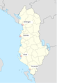 Albanian sea ports.png 411 × 600; 56 KB
-
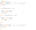
 All sensor code.png 616 × 734; 16 KB
-
 Anemometer readings.jpg 720 × 480; 61 KB
-
 Arduino cables.jpg 2,448 × 3,264; 2.41 MB
-
 Arm Gear components..JPG 1,936 × 2,592; 2.23 MB
-
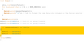
 Array code 2 error.png 823 × 111; 10 KB
-
 Array code 2.png 1,436 × 696; 36 KB
-
 Array code.png 976 × 210; 6 KB
-
 Assembled plexiglass.jpg 3,264 × 2,448; 2.54 MB
-
 ATIVIDADESFORADOBAIRRO miguelaltheman.jpg 1,200 × 800; 39 KB
-
 Attaching the bracket.JPG 480 × 640; 118 KB
-
 Attaching the guides.JPG 720 × 960; 256 KB
-
 Attachment hook.JPG 3,264 × 2,448; 1.03 MB
-
 Auto-Syringe pos 1, pos 2.jpg 716 × 960; 80 KB
-
 AVALIACAO.jpg 1,200 × 800; 40 KB
-
 BadScan2.png 1,366 × 768; 208 KB
-
 Bairro Brasilandia.jpg 1,200 × 800; 64 KB
-
 Bars with toothpicks.JPG 1,936 × 2,592; 2.3 MB
-
 Battery.JPG 3,072 × 2,304; 1.59 MB
-
 Big solder345.JPG 3,264 × 2,448; 3.61 MB
-
 BIS-SS-2013-Digital-01.jpg 960 × 720; 169 KB
-
 BIS-SS-2013-Digital-02.jpg 960 × 720; 167 KB
-
 BIS-SS-2013-Digital-03.jpg 960 × 720; 189 KB
-
 Bit-ly-example.png 602 × 163; 28 KB
-
 Black clip to hold black gear..jpg 597 × 800; 111 KB
-
 Black gear components.jpg 800 × 597; 116 KB
-
 Blob of PLA.jpg 3,264 × 1,836; 1.19 MB
-
 Both resister connected without solder by copper wire.jpg 3,264 × 2,448; 3.21 MB
-
 Bracket Ortho.png 1,131 × 692; 18 KB
-
 Bracket re-orient.jpg 4,160 × 2,340; 3.05 MB
-
 Bracket re-orienting.jpg 4,160 × 2,340; 3.43 MB
-
 Bracket.jpg 408 × 306; 20 KB
-
 Breakdown prototype 2.JPG 3,264 × 2,448; 1.98 MB
-
 Bridge case 2d design.png 1,347 × 963; 84 KB
-
 Broken bushing new bushing.jpg 478 × 640; 74 KB
-
 CannonSVG.svg 84 × 63; 3 KB
-
 Cap opt historique figure3.jpg 824 × 519; 82 KB
-
 Cap opt historique figure5.jpg 1,008 × 712; 95 KB
-
 Cap opt historique figure6.jpg 794 × 623; 53 KB
-
 Capteur composite.jpg 993 × 254; 29 KB
-
 Clamp Strandbeest.jpg 2,448 × 3,264; 1.75 MB
-
 Cleaned up.jpg 3,264 × 1,836; 1.28 MB
-
 CloudPointData.png 1,654 × 1,582; 254 KB
-
 Components of gear and new bushing.jpg 478 × 640; 68 KB
-
 CONDUCAO.jpg 1,200 × 800; 37 KB
-
 Cooling System Design.JPG 960 × 720; 303 KB
-
 Coque.JPG 229 × 122; 4 KB
-
 CUSTOBENEFICIO.jpg 1,200 × 800; 35 KB
-
 Cutting job done by wire cutter.jpg 2,448 × 3,264; 3.63 MB
-
 DB 15 Connector to Joystick.jpg 3,264 × 2,448; 2.58 MB
-
 Dc motor coding.png 485 × 275; 7 KB
-
 Description fonction.jpg 424 × 376; 41 KB
-
 Dimensions of motor.jpg 2,000 × 3,552; 2.58 MB
-
 Dismental parts of stirling Engine.jpg 3,264 × 2,448; 3.29 MB
-
 Display tank 1.JPG 3,872 × 2,592; 4.34 MB
-
 Display tank.JPG 2,592 × 3,872; 4.48 MB
-
 Dorion wall.png 661 × 724; 21 KB
-
 Driving trail.jpg 1,430 × 834; 498 KB
-
 EMPREGO.jpg 1,200 × 800; 33 KB
-
 Ensino Brasilandia.jpg 1,200 × 800; 49 KB
-
 Example of a Four Mesh Computational Domain.png 530 × 380; 86 KB
-
 Experiment 1.JPG 3,264 × 2,448; 1.64 MB
-
 Experiment 2.JPG 2,448 × 3,264; 2.08 MB
-
 Experiment 3 (successful).JPG 2,448 × 3,264; 1.62 MB
-
 Experiment 3.JPG 2,448 × 3,264; 1.46 MB
-
 Experiment 4.JPG 2,448 × 3,264; 1.7 MB
-
 Experiment 5( without voltage supply).JPG 2,448 × 3,264; 1.64 MB
-
 Experiment 5.JPG 2,448 × 3,264; 1.7 MB
-
 FACILIDADELOCOMOCAO.jpg 1,200 × 800; 38 KB
-
 Fan mount 2.jpg 3,264 × 2,448; 3.4 MB
-
 Fan mount.jpg 3,264 × 2,448; 3.35 MB
-
 Faraday Induction.jpg 3,264 × 1,840; 748 KB
-
 Fe1.s11.tm7.HW3.fig3.6.png 537 × 324; 9 KB
-
 FEAHW1.JPG 513 × 183; 16 KB
-
 FEAHW1FBD.jpg 263 × 173; 16 KB
-
 FEAHW2.JPG 474 × 163; 15 KB
-
 FEAHW2fbd.jpg 272 × 75; 13 KB
-
 Fig 1..jpg 1,536 × 2,048; 734 KB
-
 Filament anemometer.jpg 408 × 306; 17 KB
-
 File-Sumup.svg 375 × 250; 18 KB
-
 Final output voltage checks 2.jpg 1,536 × 2,048; 724 KB
-
 Final output voltage checks 3.jpg 1,536 × 2,048; 742 KB
-
 Final output voltage checks 4.jpg 1,536 × 2,048; 720 KB
-
 Final piece plexiglass.jpg 3,264 × 2,448; 2.19 MB
-
 Final wiring.jpg 1,278 × 720; 252 KB
-
 Finished Prototype of bracket.jpg 4,160 × 2,340; 3.36 MB
-
 First method.jpg 1,278 × 720; 229 KB
-
 Flap or rubber parts.JPG 3,072 × 2,304; 1.47 MB
-
 Fr635017909307330000.jpg 1,024 × 1,024; 503 KB
-
 Front View of speed control and On Off switch.jpg 2,448 × 3,264; 2.01 MB
-
 Gasket removed.JPG 1,936 × 2,592; 1.67 MB
-
 GASTOTRANSPORTE.jpg 1,200 × 800; 40 KB
-
 Get the battery.JPG 4,320 × 3,240; 4.38 MB
-
 GetNormals.png 931 × 872; 100 KB
-
 Goal.JPG 448 × 115; 6 KB
-
 Goal1.JPG 522 × 348; 17 KB
-
 Google+.JPG 1,008 × 559; 71 KB
-
 Gray with electrical tape.JPG 4,320 × 3,240; 4.72 MB
-
 Green and black wire connected to the switch.jpg 2,048 × 1,536; 931 KB
-
 Grouper et nommer les activités.svg 744 × 600; 111 KB
-
 HCCENES100.png 768 × 614; 460 KB
-
 Heat1drod.jpg 550 × 324; 22 KB
-
 Heatgun and shrinkwrap.JPG 3,264 × 2,448; 2.31 MB
-
 Heavy duty stapler.JPG 240 × 320; 26 KB
-
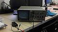
 Hitachi Oscilloscope v-212.jpg 1,289 × 761; 280 KB
-
 Home made wall (19).jpg 1,836 × 3,264; 2.03 MB
-
 Home made wall (2).jpg 1,836 × 3,264; 3.05 MB
-
 Home made wall (3).jpg 1,836 × 3,264; 1.93 MB
-
 Home made wall (4).jpg 1,836 × 3,264; 2.11 MB
-
 Home made wall (5).jpg 1,836 × 3,264; 1.79 MB
-
 Home made wall (6).jpg 1,836 × 3,264; 1.98 MB
-
 Home made wall (7).jpg 1,836 × 3,264; 2.25 MB
-
 Home made Wall.jpg 1,836 × 3,264; 2.88 MB
-
 Homemade wall (8).jpg 1,836 × 3,264; 1.54 MB
-
 Homemade wall (9).jpg 1,836 × 3,264; 1.56 MB
-
 Honeycomb.2.jpg 3,264 × 2,448; 3.47 MB
-
 Honeycomb.wind.jpg 3,264 × 2,448; 2.85 MB
-
 Hotwire anemometer.jpg 3,264 × 2,448; 2.42 MB
-
 Hovercraft prototype 2.PNG 948 × 619; 139 KB
-
 Hovercraft prototype.PNG 976 × 692; 256 KB
-
 HWR-BIS-22-04-2013-3.01.jpg 720 × 960; 182 KB
-
 HWR-BIS-22-04-2013-3.02.jpg 720 × 960; 191 KB
-
 HWR-BIS-22-04-2013-3.03.jpg 960 × 720; 197 KB
-
 HWR-BIS-22-04-2013-3.04.jpg 960 × 720; 220 KB
-
 HWR-BIS-22-04-2013-3.05.jpg 960 × 720; 180 KB
-
 HWR-BIS-22-04-2013-3.06.jpg 720 × 960; 184 KB
-
 Ibirapueraa.jpg 800 × 532; 160 KB
-
 IDADE.jpg 1,200 × 800; 46 KB
-
 Idea 1 metal bracket.jpg 2,340 × 4,160; 3.05 MB
-
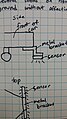
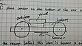 Idea 2 sensor on bottom.jpg 4,160 × 2,340; 3.26 MB
-
 Idea 3 two sensors.jpg 4,160 × 2,340; 3.44 MB
-
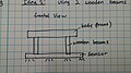 Idea 4 wooden beam front view.jpg 4,160 × 2,340; 2.96 MB
-
 Idea 4 wooden beam side view.jpg 4,160 × 2,340; 2.93 MB
-
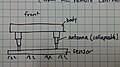
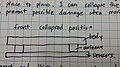 Idea 5 antenna collapsed.jpg 4,160 × 2,340; 2.89 MB
-
 Idea 5 antenna front view.jpg 4,160 × 2,340; 3.08 MB
-
 Idea 5 antenna side view.jpg 4,160 × 2,340; 3.13 MB
-
 If statement code (2).png 616 × 537; 11 KB
-
 If statement code.png 823 × 698; 17 KB
-
 If statement.png 1,093 × 553; 16 KB
-
 IMAG0060.jpg 2,560 × 1,440; 435 KB
-
 IMAG010911.jpg 1,440 × 2,560; 444 KB
-
 IMAG0112.jpg 2,560 × 1,440; 486 KB
-
 IMAG0740-1.jpg 1,360 × 1,088; 164 KB
-
 Input mic jack..JPG 1,936 × 2,592; 2.04 MB
-
 InstallingDrivers.jpg 1,616 × 1,582; 340 KB
-
 Internals of motor.jpg 478 × 640; 100 KB
-
 Inventor(3 KHZ-180VOLT).jpg 600 × 600; 92 KB
-
 Irrigation System for Cavitation Machine.svg 765 × 990; 35 KB
-
 Kinect drivers.jpg 1,168 × 404; 65 KB
-
 L 2.jpg 1,920 × 2,560; 542 KB


.JPG)


.JPG)


.jpg)
.jpg)
.jpg)
.jpg)
.jpg)
.jpg)
.jpg)

.jpg)
.jpg)


.png)


.jpg)

