File:Simplest crystal radio circuit.svg
Jump to navigation
Jump to search

Size of this PNG preview of this SVG file: 402 × 600 pixels. Other resolutions: 161 × 240 pixels | 322 × 480 pixels | 515 × 768 pixels | 686 × 1,024 pixels | 1,372 × 2,048 pixels | 691 × 1,031 pixels.
Original file (SVG file, nominally 691 × 1,031 pixels, file size: 11 KB)
Captions
Captions
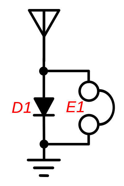
Circuit of the first crystal radios
Summary[edit]
| Description |
English: Circuit of the simplest possible crystal radio receiver. Circuits of this type were used in the first experimental crystal radio receivers in the pioneering days of radio, just after 1900. It consists of a crystal detector (semiconductor diode) DI connected between a long wire antenna and ground, with a sensitive earphone E1 attached across it. The diode rectifies the radio signals picked up by the antenna by conducting the RF current moving in one direction to ground, leaving a pulsing DC voltage across the detector. This extracts the audio signal from the radio frequency carrier wave, and the earphone converts the audio current to sound. Since it lacks a tuned circuit or any other frequency-selective element besides the broad resonance of the antenna, this circuit has no ability to select a single radio signal to receive, out of all the signals picked up by the antenna. So all radio stations picked up by the antenna are heard simultaneously in the earphone (in practice, the most powerful station usually drowns out the rest). |
| Date | |
| Source | Own work |
| Author | Chetvorno |
| SVG development | This diagram was created with Inkscape, or with something else. This diagram uses translateable embedded text. |
Licensing[edit]
I, Chetvorno, release this work into the public domain, for any use whatever.
| This work has been released into the public domain by its author, Chetvorno at English Wikipedia. This applies worldwide. In some countries this may not be legally possible; if so: Chetvorno grants anyone the right to use this work for any purpose, without any conditions, unless such conditions are required by law. |
File history
Click on a date/time to view the file as it appeared at that time.
| Date/Time | Thumbnail | Dimensions | User | Comment | |
|---|---|---|---|---|---|
| current | 04:01, 9 May 2017 | | 691 × 1,031 (11 KB) | Chetvorno (talk | contribs) | Replaced invalid Inkscape SVG version with "plain SVG" version that passes validation |
| 02:37, 28 January 2016 |  | 691 × 1,031 (15 KB) | Chetvorno (talk | contribs) | Increased line width | |
| 06:57, 20 May 2010 |  | 744 × 1,052 (16 KB) | Chetvorno (talk | contribs) | {{Information |Description={{en|Circuit of very simple crystal radio receiver. Circuits of this type were used in the first experimental crystal radio receivers in the pioneering days of radio, just after 1900. It consi |
You cannot overwrite this file.
File usage on Commons
There are no pages that use this file.
File usage on other wikis
The following other wikis use this file:
- Usage on en.wikipedia.org
- Usage on es.wikipedia.org
- Usage on fa.wikipedia.org
- Usage on fi.wikipedia.org
- Usage on fr.wikipedia.org
- Usage on pnb.wikipedia.org
- Usage on vi.wikipedia.org