File:Seeds oils extracting machine.png
Seeds_oils_extracting_machine.png (553 × 175 pixels, file size: 62 KB, MIME type: image/png)
Captions
Captions
Summary
[edit]
| Description |
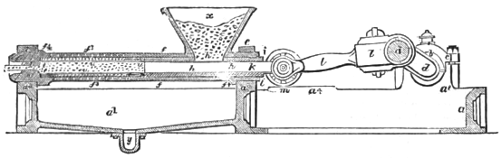
Français : Presse brevetée en mai 1849 par H. Bessemer et E. Heywood, pour extraire les huiles de graines.
English: A patent was taken out in May, 1849, by Messrs. Bessemer & Heywood, for a machine to be used for expressing oils from seeds. Fig. 467 is a drawing of it. The bedplate of framing, a, which should be cast in one piece, forms, at a', a cistern for the reception of the oily matters which fall therein as they are expressed. At the opposite end of the bedplate tliere are formed projections, a2, in which brasses, b, are fitted, and with the caps, c, form bearings for the crank shaft, d, to turn in. There are also two other projections, a3, a3 cast on to the bebplate, and are provided with caps, e, in a similar manner to the caps of plummer blocks. These caps are for the purpose of retaining firmly in its place the pressing cylinder, f, which should be made of tough gun-metal, and of such thickness as to be capable of withstanding a considerable amount of internal pressure. Within the cylinder, f, is fitted a lining, which consists of a gun-metal tube, n, having a spiral groove, r,
cut on the outside of it, and presenting the appearance of an ordinary square-threaded screw. At very short intervals all along the spiral groove there are conical holes, s, drilled through the tube, n, and communicating with the interior of it. At n' the inside of the tube is enlarged, and is provided with a steel collar, t. The opposite end of the tube at n' is reduced in diameter, and is provided externally with a steel collar, u. A plain cylindrical bag T, with open ends, formed of fustian, hair-cloth, or similarly pervious material, is made of such a diameter as will fit closey to the inside of the tube n ; and within this bag is placed a cylinder, w, of wire gauze or finely perforated metal. The steel collar t is forced into the end of the wire gauze, by which it becomes driven into the recess formed at n', and is securely held there by the pressure of the collar t. The bag v and wire gauze w are then tightly stretched over the end u2 of the tube, and the collar u driven tightly on, by which means the bag and wire gauze are securely held in their places. The lining tube n is then put into the pressing cylinder as far as the shoulder g. A tubular piece h is next put in and brought into contact with the collar u and then the gland i is screwed home, whereby the lining n is firmly retained within the pressing cylinder. The end of the pressing cylinder is contracted at f', and forms a shoulder for the abutment of the collar J, the diameter of the aperture in which regulates the pressure to which the matters under operation are subjected. Within the tube n there is fitted a solid plunger k, which receives motion from the crank d by means of the connecting rod l, the parallel motion being obtained by the wheels m, on the cross-head o, traversing on the side of the bedplate at a4. x is a hopper, bolted to a flange f2 on the pressing cylinder, and communicating therewith. There is also an opening in the tube n at n' corresponding with the opening into the hopper, so that any materials placed into the hopper may fall into the tube n, when the plunger k is withdrawn from beneath the opening. At that part of the pressing cylinder which is occupied by the " lining," there are drilled numerous small holes, f3, which communicate at various points with the spiral groove in the tube n. On the outside of the pressing cylinder there are formed two collars, f4, f4, which abut against the projecting pieces a3 and caps e, and cause the pressing cylinder to be retained firmly in its place. When steam power is to be employed to give motion to the oil press, it is preferable to have the crank which is actuated by the steam piston formed on the end d', on the crank shaft of the oil press, and placed at such an angle to the crank d, that when the crank d is pushing the plunger k to the end of its stroke, the steam piston will be at the half stroke, whereby the motive power applied will be the greatest at the time that the press offers the most resistance, and the steam piston also, when passing its dead points, will have to overcome the friction of the machinery only, as the plunger k will be in the middle of its back stroke. When any other motive-power is applied to turn the crank d, it will be necessary to put a fly-wheel on the shaft d' as also such cog-wheels as will be necessary to connect it with the first mover. When this apparatus is to be employed in expressing linseed oil, the seed, after having been ground and treated in the way now commonly practiced, is put into the hopper, and motion being transmitted to the crank in the manner before described, the plunger k will commence a reciprocating movement in the tube u of the pressing cylinder. Each time that it recedes in the direction of the crank it will move from under the opening in the hopper, and allow a portion of the seed to fall into the tube, while the reverse motion of the plunger will drive it towards the open end of the cylinder, its passage being much retarded by the friction against the sides of the tube lining, but chiefly by the con- traction of. the escape aperture through the collar j, which will produce a considerable amount of resistance, and consequently the plunger will have to exert an amount of pres- sure upon the seed in proportion as the escape aperture is made larger or smaller. The collar j is made movable, and by withdrawing the plunger entirely from the tube, it can be exchanged at any time for another having a larger or smaller opening. The lining may at any time be removed from the cylinder, and the worn parts removed when found requisite. The action of the plunger is somewhat like that of the plunger of a hydraulic press pump, the seeds being pumped in at one end of the pressing cylinder, and allowed to escape at the other, while the whole of the interior of the pressing cylinder that contains seed is lined with hair-cloth or other suitable pervious material, and, that it may be protected from injury, is covered with wire gauze or finely perforated metal. The bag is thus completely defended from within, while it is supported at every part by the tube n on the outside, and is thus subjected to a very little wear and to no risk of bursting. The expressed oil, passing through the wire gauze and bag, finds its way through the perforation s into the spiral channel r, and from thence it finds ready egress by the perforations f3 in the pressing cylinder, and as it falls is received by the cistern a', from which it can be drawn by the pipe y. Two or more presses may be used side by side, actuated either by one crank throw or by separate throws upon one shaft, placed with reference to each other in such manner as greatly to equalize the amount of resistance throughout the revolution of the crank shaft. Although the one here described is a cylindrical pressing plunger, an angular section may he given to the pressing vessel and plunger, and may of course be used to express oils from any seeds containing them. In the drawing, no method is shown for heating the seed cake to be subjected to pressure therein, but as it is known to be desirable to heat some matters from which oil is to be expressed, the following method is described : — When heat is to be applied during the process of pressing, it is desirable to make the pressing cylinder of some-what larger diameter, and of greater length, and to divide the cistern a' into two separate compartments, over both of which the pressing cylinder is to extend ; a strong wrought-iron tube is to enter the open end of the pressing cylinder, and to extend about half-way to the hopper, where it terminates in a solid pointed end ; this tube is to occupy the centre of the pressing cylinder, and will consequently leave an annular space around it, which will be occupied by the seed, meal, or other matters under operation. Steam is let into this iron tube, and its temperature thereby raised to any desired point. The end of the tube which extends beyond the pressing cylinder is to be securely attached to a bracket projecting from the bedplate, so that it may be firmly held in its position, notwithstanding the force exerted against the pointed end of it. The effect of this arrangement will be, that, as the seed, meal, etc., fall into the pressing cylinder and are pushed forward by the plunger, they will give out a portion of their oil in that state known as cold drawn, which will fall into the first compartment of the cistern a'. The further progress of the meal along the pressing cylinder will bring it in contact with the pointed end of the heating tube •, here it will have to divide itself, and pass along the annular space between the heating tube and the lining, and being thus spread into a thin cylindrical layer around the tube, it will readily absorb heat therefrom, when a second portion of oil will be given out and received by the second compartment of the cistern ; and thus will the operations of cold and hot pressing be carried on simultaneously. |
| Date | |
| Source | A supplement to Ure's Dictionary of Arts, Manufactures, and Mines, - containing a clear exposition of their principles and practice, p.816 |
| Author | Robert Hunt (1807-1887) |
Licensing
[edit]
|
This work is in the public domain in its country of origin and other countries and areas where the copyright term is the author's life plus 70 years or fewer. This work is in the public domain in the United States because it was published (or registered with the U.S. Copyright Office) before January 1, 1929. | |
| This file has been identified as being free of known restrictions under copyright law, including all related and neighboring rights. | |
|
This work is in the public domain in its country of origin and other countries and areas where the copyright term is the author's life plus 100 years or fewer. | |
| This file has been identified as being free of known restrictions under copyright law, including all related and neighboring rights. | |
File history
Click on a date/time to view the file as it appeared at that time.
| Date/Time | Thumbnail | Dimensions | User | Comment | |
|---|---|---|---|---|---|
| current | 19:38, 13 January 2018 | 553 × 175 (62 KB) | Borvan53 (talk | contribs) | User created page with UploadWizard |
You cannot overwrite this file.
File usage on Commons
There are no pages that use this file.