File:Pc-psu inner.JPG

From Wikimedia Commons, the free media repository
Jump to navigation Jump to search

Original file(2,272 × 1,704 pixels, file size: 1,012 KB, MIME type: image/jpeg)

Captions

Captions

Add a one-line explanation of what this file represents

Summary[edit]

Description
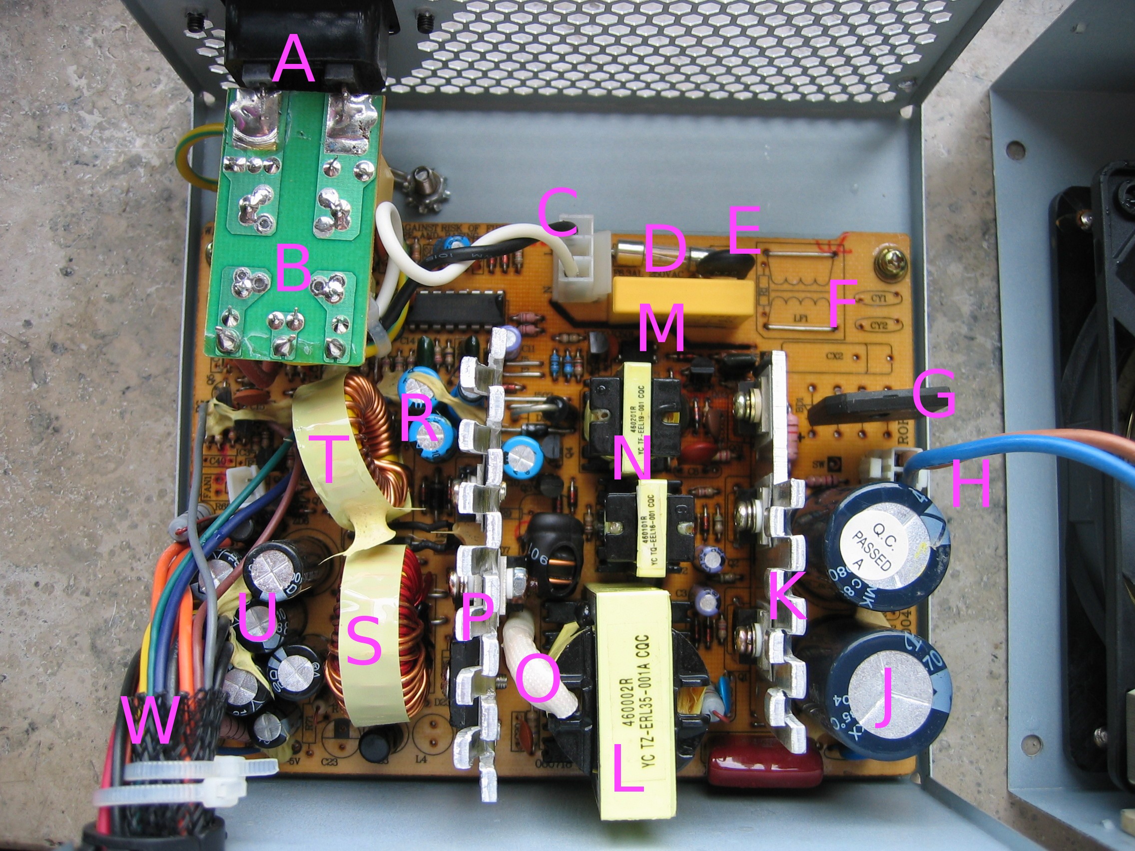
English: Inside ATX PC power supply
A - AC Input ( 230 V AC )
B - Net Filter and chassis ground wire (yellow/green), to chassis screw
C - AC filtered input
D - Fuse
E - NTC to limit the startup current
F - Filter bypassed with two wires and moved to B to provide space for the PFC choke
G - Rectifier
H - PFC-choke connector, black marks SW for 115 V switch (not installed in this sample)
J - Primary smoothing capacitors 2x 200 V
K - Heat sink switching transistors
L - Main transformer
M - Optocouppler
N - Standby transformer
O - Common wire bunch - ground - transformer coils secondary side
P - Heat sink secondary rectifier
R - 5 V-SB smoothing capacitors
S - 5 V and 12 V choke
T - 3.3 V choke
U - Smoothing capactors for 3.3 V, 5 V, 12 V - two each (these have the highest ripple current load)
W - Output harness
Left to K: Timing capacitors, a failure will blow Q1/Q2 and trigger the fuse
Between L and N: feedback-oscillator-couppler
Between N and O: 5 V to 3.3V shifting choke
White Plug next to T: internal fan motor
Between L and W: (not connected L4 and C23) not used -5 V
Deutsch: Im Innern eines PC-Netzteils
A - Wechselspannungseingang ( 230 V AC )
B - Netzspannungsfilter und Gehäuseerdungsleitung (Grün-Gelb), zur Gehäuseschraube
C - Gefilterte Netzspannung
D - Sicherung
E - NTC - Heißleiter zu Einschaltstrombegrenzung
F - Überbrückter Netzfilter, wurde nach B verlegt, um der PFC-Drossel Platz zu bieten
G - Gleichrichter
H - Anschluss für PFC-Drossel. SW sind die schwarz markierten Anschlüsse für den 115 V Eingangsspannungsschalter (In diesem Exemplar nicht eingebaut)
J - Primäre Glättungskondensatoren 2x 200 V
K - Kühlkörper für Schalttransistoren
L - Haupttransformator
M - Optokoppler
N - Standby Transformator
O - Gebündelte Enden der Sekundärwicklungen - Masse (0 V)
P - Kühlkörper für Sekundärgleichrichter
R - 5 V-SB Glättungskondensatoren
S - 5 V und 12 V Speicherdrossel
T - 3.3 V Speicherdrossel
U - Glättungskondensatoren für 3.3 V, 5 V, 12 V - jeweils zwei (diese unterliegen der intensivsten Belastung durch Mischstrom)
W - Ausgangskabelbaum
Links von K: Zeitgliedkondensatoren; ein Ausfall zerstört Q1/Q2 und löst die Sicherung aus
Zwischen L und N: Rückkopplungsübertrager
Zwischen N und O: 5 V auf 3.3V Phasenschieberdrossel
Weiser Anschluss neben T: Interner Lüftermotor
Zwischen L und W: (nicht bestückt L4 und C23) nicht geschaltete -5 V
Date
Source Own work
Author Hans Haase

Licensing[edit]

I, the copyright holder of this work, hereby publish it under the following license:
w:en:Creative Commons
attribution share alike
This file is licensed under the Creative Commons Attribution-Share Alike 3.0 Unported license.
You are free:
  • to share – to copy, distribute and transmit the work
  • to remix – to adapt the work
Under the following conditions:
  • attribution – You must give appropriate credit, provide a link to the license, and indicate if changes were made. You may do so in any reasonable manner, but not in any way that suggests the licensor endorses you or your use.
  • share alike – If you remix, transform, or build upon the material, you must distribute your contributions under the same or compatible license as the original.
Annotations
InfoField
This image is annotated: View the annotations at Commons

File history

Click on a date/time to view the file as it appeared at that time.

Date/TimeThumbnailDimensionsUserComment
current14:36, 11 June 2012Thumbnail for version as of 14:36, 11 June 20122,272 × 1,704 (1,012 KB)Hans Haase (talk | contribs)

There are no pages that use this file.

File usage on other wikis

The following other wikis use this file:

Metadata