File:Op-Amp Instrumentation Amplifier.svg
Jump to navigation
Jump to search

Size of this PNG preview of this SVG file: 512 × 410 pixels. Other resolutions: 300 × 240 pixels | 600 × 480 pixels | 959 × 768 pixels | 1,279 × 1,024 pixels | 2,558 × 2,048 pixels.
Original file (SVG file, nominally 512 × 410 pixels, file size: 8 KB)
Captions
Captions
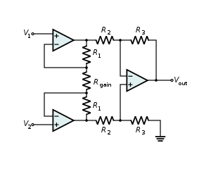
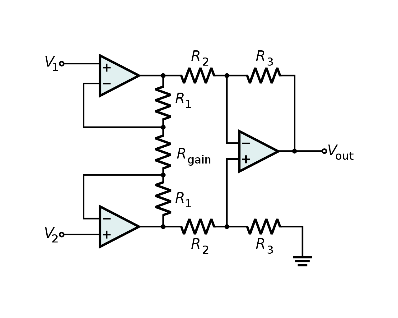
A circuit diagram of an instrumentation amplifier made using operational amplifiers
| Description | A circuit diagram of an instrumentation amplifier made using operational amplifiers. Combines very high input impedance, high common-mode rejection, low DC offset, and other properties used in making very accurate, low-noise measurements |
| Date | |
| Source | Own work |
| Author | Inductiveload |
| Permission (Reusing this file) |
Own work, all rights released (Public domain) |
| Other versions |
 |
| SVG development |
| I, the copyright holder of this work, release this work into the public domain. This applies worldwide. In some countries this may not be legally possible; if so: I grant anyone the right to use this work for any purpose, without any conditions, unless such conditions are required by law. |
File history
Click on a date/time to view the file as it appeared at that time.
| Date/Time | Thumbnail | Dimensions | User | Comment | |
|---|---|---|---|---|---|
| current | 22:38, 8 May 2022 | | 512 × 410 (8 KB) | Gutten på Hemsen (talk | contribs) | Added white background, added greater margins, optimized source, added responsive scaling |
| 19:52, 18 February 2009 |  | 400 × 300 (54 KB) | Inductiveload (talk | contribs) | flipped op amp | |
| 04:14, 26 January 2009 |  | 400 × 300 (54 KB) | Inductiveload (talk | contribs) | {{Information |Description=A circuit diagram of a en:instrumentation amplifier made using en:operational amplifiers. Combines very high input impedance, high common-mode rejection, low DC offset, and other properties used in making |
You cannot overwrite this file.
File usage on Commons
The following 4 pages use this file:
File usage on other wikis
The following other wikis use this file:
- Usage on ca.wikipedia.org
- Usage on en.wikipedia.org
- Usage on en.wikibooks.org
- Usage on et.wikipedia.org
- Usage on fa.wikipedia.org
- Usage on fi.wikipedia.org
- Usage on fr.wikibooks.org
- Usage on hi.wikipedia.org
- Usage on uk.wikipedia.org
- Usage on vi.wikipedia.org
- Usage on www.wikidata.org
- Usage on zh.wikipedia.org