File:Heatpump.svg
Jump to navigation
Jump to search

Size of this PNG preview of this SVG file: 750 × 438 pixels. Other resolutions: 320 × 187 pixels | 640 × 374 pixels | 1,024 × 598 pixels | 1,280 × 748 pixels | 2,560 × 1,495 pixels.
Original file (SVG file, nominally 750 × 438 pixels, file size: 34 KB)
Captions
Captions
Add a one-line explanation of what this file represents
Summary[edit]
| Description |
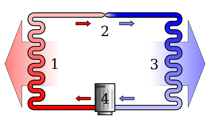
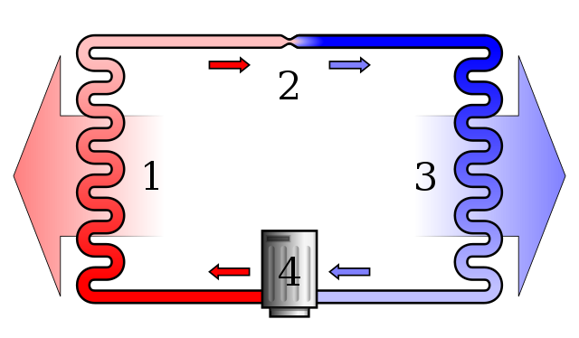
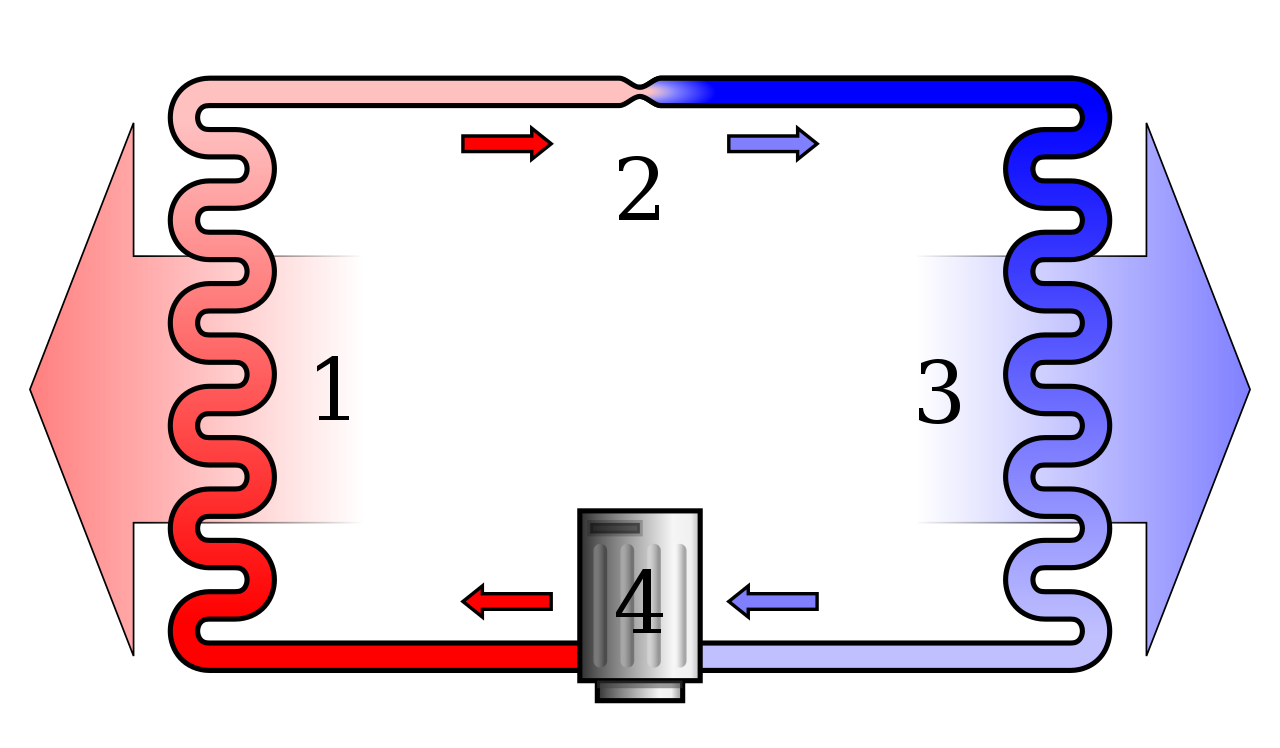
English: Diagram of a phase change heat pump.
Note that the arrows in the diagram are meant to indicate the flow of air and coolant; they do not correspond to heat flow, which in the system depicted is (generally) from right to left. Deutsch: Schema einer Wärmepumpe mit Phasenwechsel. |
| Source | Own work |
| Author | Ilmari Karonen |
| SVG development | This diagram was created with Inkscape…important. This diagram uses embedded text/digits. |
Legend[edit]
- Condenser coil (hot side heat exchanger, gas cools and liquifies)
- Metering Device (liquid expands and cools)
- Evaporator coil (cold side heat exchanger, liquid vaporizes and heats up)
- Compressor (gas is compressed and heats up)
- Red = Gas at high pressure and very high temperature
- Pink = Liquid at high pressure and high temperature
- Blue = Liquid at low pressure and very low temperature
- Light Blue = Gas at low pressure and low temperature
Licensing[edit]
| I, the copyright holder of this work, release this work into the public domain. This applies worldwide. In some countries this may not be legally possible; if so: I grant anyone the right to use this work for any purpose, without any conditions, unless such conditions are required by law. |
File history
Click on a date/time to view the file as it appeared at that time.
| Date/Time | Thumbnail | Dimensions | User | Comment | |
|---|---|---|---|---|---|
| current | 09:22, 5 April 2017 | | 750 × 438 (34 KB) | Jahobr (talk | contribs) | cleanup, I hope errors are fixed |
| 08:20, 13 December 2007 |  | 750 × 438 (63 KB) | No-w-ay (talk | contribs) | Reverted to version as of 20:49, 12 December 2005 | |
| 16:07, 12 December 2007 |  | 750 × 438 (51 KB) | No-w-ay (talk | contribs) | Reverted to version as of 20:27, 12 December 2005 | |
| 16:06, 12 December 2007 |  | 715 × 367 (88 KB) | No-w-ay (talk | contribs) | New version with the arrow in the evaporator coil reversed to show correctly the heat transfer (from outside environment to the inside fluid). | |
| 16:03, 12 December 2007 |  | 715 × 367 (88 KB) | No-w-ay (talk | contribs) | Diagram of a phase change heat pump. Drawn in Inkscape by Ilmari Karonen. New version with the arrow in the evaporator coil reversed to show correctly the heat transfer (from outside environment to the inside fluid). | |
| 20:49, 12 December 2005 |  | 750 × 438 (63 KB) | Ilmari Karonen (talk | contribs) | so close... | |
| 20:46, 12 December 2005 |  | 750 × 438 (62 KB) | Ilmari Karonen (talk | contribs) | keep trying | |
| 20:42, 12 December 2005 |  | 750 × 438 (50 KB) | Ilmari Karonen (talk | contribs) | sigh... | |
| 20:38, 12 December 2005 |  | 750 × 438 (50 KB) | Ilmari Karonen (talk | contribs) | goddammit! | |
| 20:35, 12 December 2005 |  | 750 × 438 (50 KB) | Ilmari Karonen (talk | contribs) | damnit, why can't these things render consistently? |
You cannot overwrite this file.
File usage on Commons
The following 4 pages use this file:
File usage on other wikis
The following other wikis use this file:
- Usage on af.wikipedia.org
- Usage on ar.wikipedia.org
- Usage on az.wikipedia.org
- Usage on be.wikipedia.org
- Usage on bs.wikipedia.org
- Usage on ca.wikipedia.org
- Usage on cs.wikipedia.org
- Usage on da.wikipedia.org
- Usage on en.wikipedia.org
- Usage on eo.wikipedia.org
- Usage on eo.wiktionary.org
- Usage on es.wikipedia.org
- Usage on et.wikipedia.org
- Usage on fa.wikipedia.org
- Usage on fi.wikipedia.org
- Usage on fr.wikipedia.org
- Usage on he.wikipedia.org
- Usage on hi.wikipedia.org
- Usage on hr.wikipedia.org
- Usage on hu.wikipedia.org
- Usage on hy.wikipedia.org
- Usage on id.wikipedia.org
- Usage on it.wikipedia.org
- Usage on ja.wikipedia.org
- Usage on ka.wikipedia.org
- Usage on kk.wikipedia.org
View more global usage of this file.